
Partially flooding spar buoy

a technology of spar buoys and buoys, which is applied in the field of spar buoys, can solve the problems of more material required for buoys, more expensive to ship larger and heavier buoys, and more cost, and achieve the effect of convenient handling of buoys

Inactive Publication Date: 2008-09-18
GILMAN RICHARD
View PDF7 Cites 2 Cited by
  • Summary
  • Abstract
  • Description
  • Claims
  • Application Information

AI Technical Summary

Benefits of technology

[0005]In the preferred embodiment, the buoy includes at least one flooding opening to allow water to pass therethrough into the cavity. The flooding opening is formed within a lower portion of the buoy body to be submerged under water. In the preferred embodiment, the mooring mechanism includes a plate attached to the buoy body and a mooring ring for allowing the buoy to be attached to the mooring. The mooring is attached to the buoy body by at least two bolts to ensure sturdy attachment. Additionally, in the preferred embodiment, the buoy includes at least one handle to allow more convenient handling of the buoy, wherein the handle is an opening formed within the buoy body.

Problems solved by technology

The larger buoys require more material and, thus, are more costly.
Additionally, it is more expensive to ship larger and heavier buoys.

Method used


Image

  • Partially flooding spar buoy
  • Partially flooding spar buoy
  • Partially flooding spar buoy

Examples


Embodiment Construction

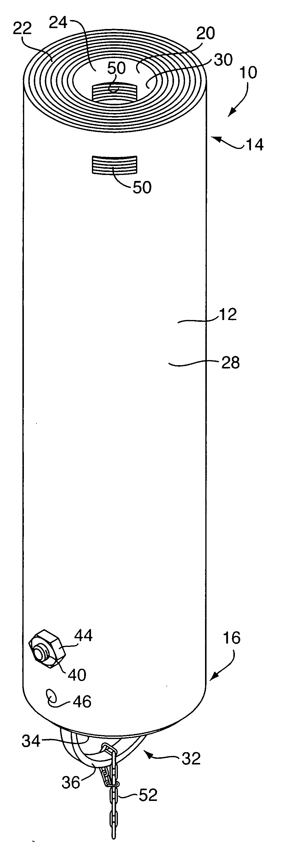
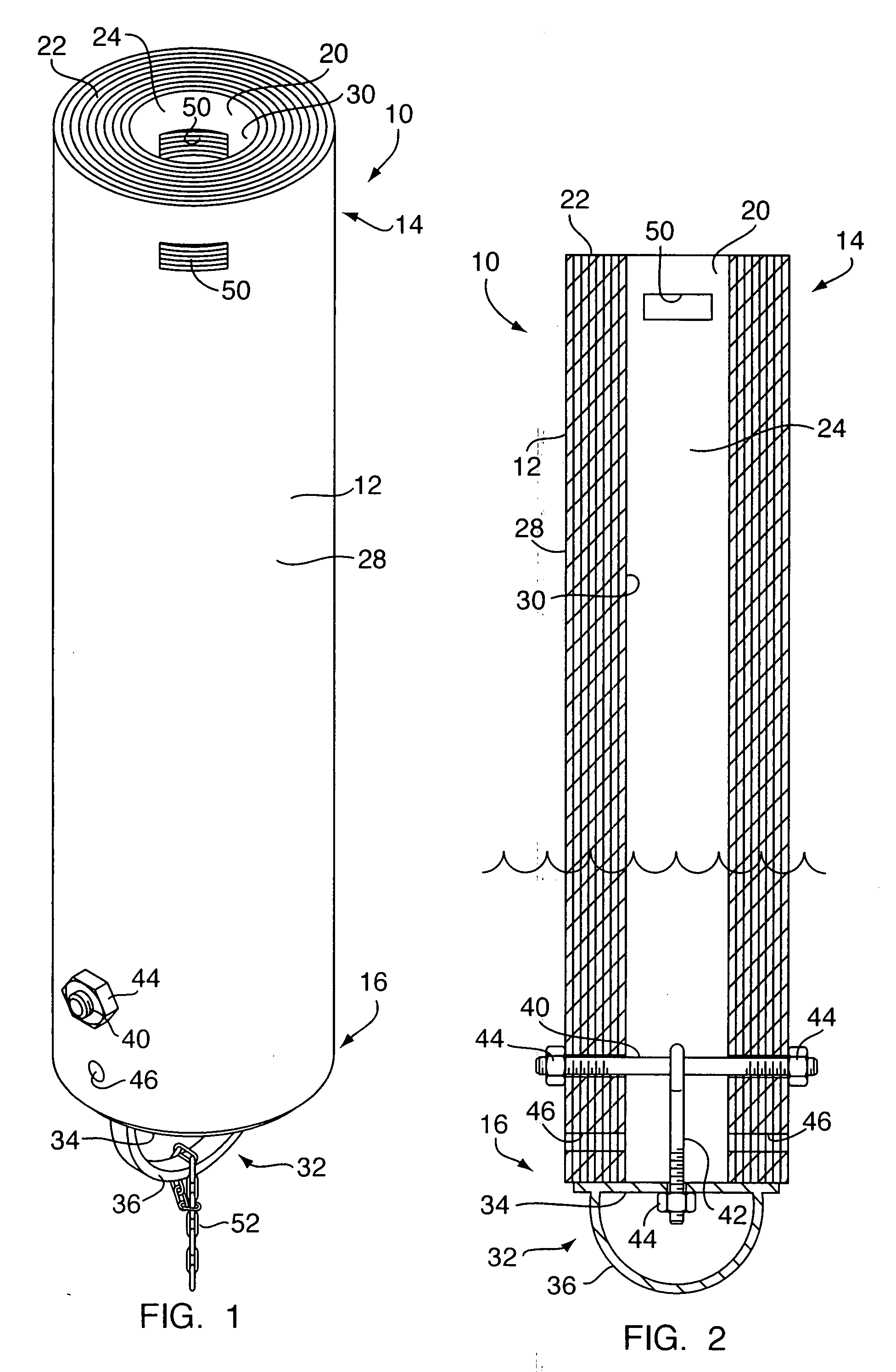
[0013]Referring to FIGS. 1 and 2, a spar buoy 10 includes a buoy body 12 having an upper portion 14 and a lower portion 16. The buoy body 12 includes a cavity 20 formed therein to define a wall 22 surrounding an inner space 24. The wall 22 comprises an outer surface 28 and an inner surface 30. In the preferred embodiment, the cavity 20 is a substantially cylindrical through opening defining a substantially cylindrical wall 22.

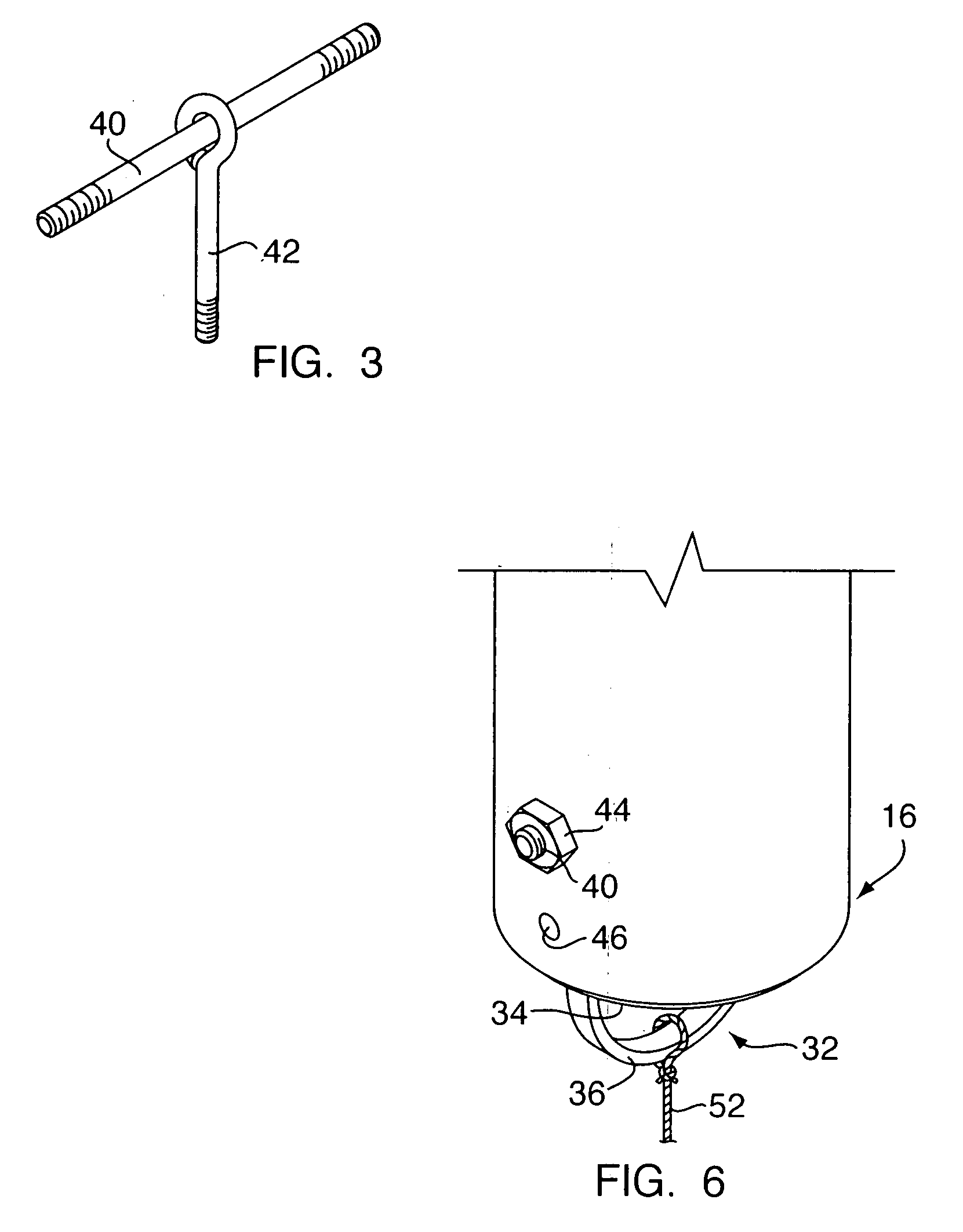
[0014]The buoy 10 also includes a mooring mechanism 32 disposed on the lower portion 16 of the buoy body 12. The moorning mechanism 32, in the preferred embodiment, includes a mooring plate 34 with a mooring ring 36. The mooring plate 34 is secured to the buoy body 12 by means of a buoy mounting including a first bolt 40 passing through the buoy body 12 and a second bolt 42 securing the mooning plate 34 to the first bolt 40, as best seen in FIG. 3. The first bolt 40 extends through the cavity 20 and walls 22. The bolts 40, 42 are secured to the buoy wall 22 and...


PUM


Abstract

A partially flooding buoy includes a buoy body having a substantially cylindrical shape defining a cavity therein and a mooring mechanism attached to the buoy body to allow the buoy to be moored. The partially flooding buoy can be partially flooded with water after the buoy is deployed. The cavity is adapted to accommodate ballast therein. The buoy also includes at least one handle to allow more convenient handling of the buoy, wherein the handle is an opening formed within the buoy body.

Description

TECHNICAL FIELD[0001]The present invention relates to buoys and, more particularly, to spar buoys.BACKGROUND OF THE INVENTION[0002]A variety of buoys are deployed for various purposes in the waterways. One type of a buoy is a spar buoy or, also referred to as, a pencil buoy. The spar or pencil buoys are typically used for marking purposes in the waterways and usually include signage thereon. The spar buoys are deployed to remain afloat upright and include a solid cylindrical body with a lower portion and an upper portion. The lower portion is typically immersed under water and the upper portion is intended to protrude above the water surface. The upper portion is utilized for various waterways makings, such as speed limits, slow down signs and other directional or warning signage.[0003]The spar buoys come in various sizes. The size of the buoy deployed depends on various factors, including the surface area required for signage. The larger buoys require more material and, thus, are m...

Claims


Application Information

Patent Timeline
Patent Type & Authority Applications(United States)
IPC IPC(8): B63B22/20
CPCB63B22/20
Inventor GILMAN, RICHARD
Owner GILMAN RICHARD
Learn More