Electronic control unit
- Summary
- Abstract
- Description
- Claims
- Application Information
AI Technical Summary
Benefits of technology
Problems solved by technology
Method used
Image
Examples
first embodiment
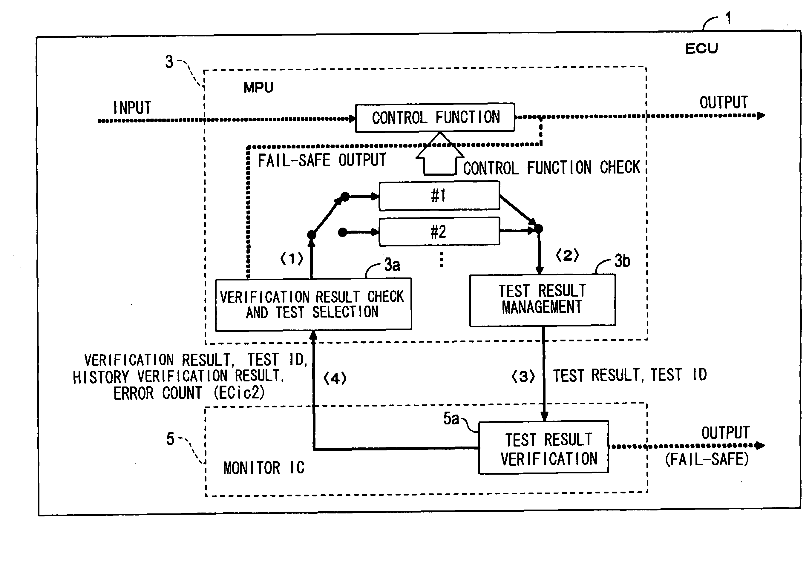
[0033]As shown in FIG. 1, an electronic control unit (ECU) 1 includes a micro-processing unit (MPU) 3 as a microcomputer that performs various processing programmed for controlling an engine of a vehicle, and a monitor IC 5 that monitors the operation of MPU 3.
[0034]The MPU 3, for example, determines the control amount of an actuator for actuating the engine based on input information from various sensors and the like, and performs control processing for achieving such various control functions. Programs for achieving control functions of such control processing are pre-stored in a ROM (not shown).
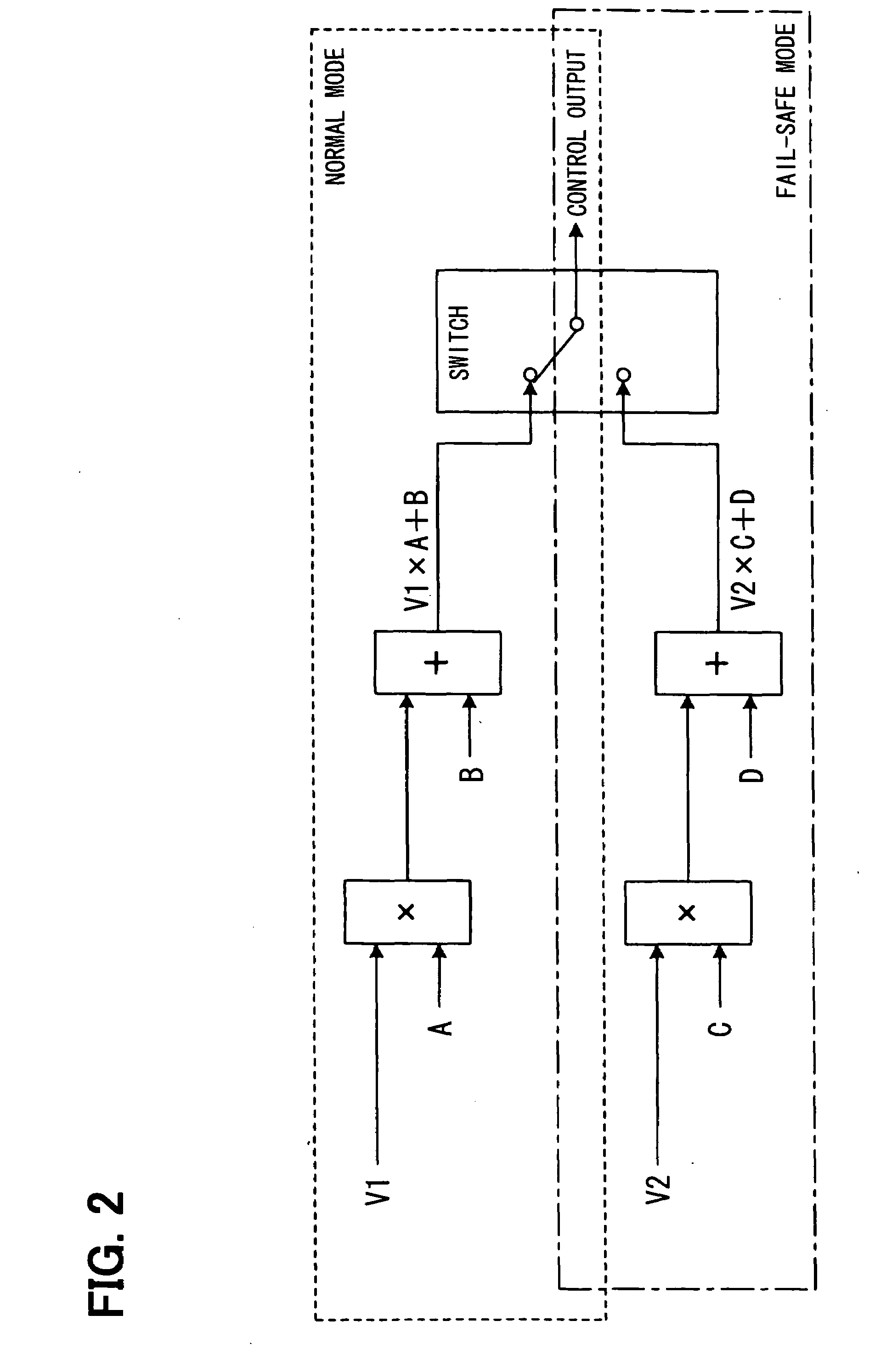
[0035]For example, as one of control functions, an actuator control amount computation function as shown in FIG. 2 is available. This actuator control amount computation function performs an operation “V1× constant A+constant B” for a voltage V1 inputted from the main signal input system, when the main of main and sub signal input systems (not shown) provided in the ECU 1 is normal and the...
second embodiment
[0110]In a second embodiment, an ECU has the same hardware configuration as the ECU 1 of the first embodiment, and hence the reference numerals of individual units are the same as those in the first embodiment.
[0111]In contrast to the ECU 1 of the first embodiment, the MPU 3 runs tests for checking whether the all test run verification function (S810 to S850) of the monitor IC 5, the function to reset the error count ECic1, and the count-up function (S715 to S725) are normal. The monitor IC 5 transmits a history verification result to the MPU 3 in S755 of FIG. 10 along with the error count ECic1. Therefore, the MPU 3 executes the processing of a verification result check and test selection unit 3a shown in FIG. 16 instead of the processing of FIG. 3. The processing of FIG. 16 is different from the processing of FIG. 3 in the following points (1-1) to (1-3).
[0112](1-1): S115 performs test ID selection processing of FIG. 17 in place of the processing of FIG. 4.
[0113](1-2): When S122 d...
third embodiment
[0131]In a third embodiment shown in FIG. 19, the ECU 1 is different from the ECU 1 of the first embodiment in the following points (2-1) to (2-5).
[0132](2-1): The monitor IC 5 includes, in addition to the test result verification unit 5a, a test result verification unit 5b having the same construction and functions as the test result verification unit 5a. The two test result verification units 5a and 5b operate in parallel.
[0133]The fail-safe signal outputted in the processing of S760 in FIG. 10 by each of the test result verification units 5a and 5b is outputted to the outside of the monitor IC 5 via an OR circuit 5c. In short, if at least one of two test result verification units 5a and 5b outputs the fail-safe signal, the signal is outputted from the monitor IC 5 to reduce the output of the engine. An AND circuit may be provided in place of the OR circuit 5c. The two test result verification units 5a and 5b correspond to plural circuit blocks.
[0134](2-2): The MPU 3 performs the ...
PUM
 Abstract
Description
Claims
Application Information
 - R&D
- Intellectual Property
- Life Sciences
- Materials
- Tech Scout
- Unparalleled Data Quality
- Higher Quality Content
- 60% Fewer Hallucinations
Browse by: Latest US Patents, China's latest patents, Technical Efficacy Thesaurus, Application Domain, Technology Topic, Popular Technical Reports.
© 2025 PatSnap. All rights reserved.Legal|Privacy policy|Modern Slavery Act Transparency Statement|Sitemap|About US| Contact US: help@patsnap.com


