Back Pressure Regulator

a back pressure regulator and pressure regulator technology, applied in the direction of fluid pressure control, process and machine control, instruments, etc., can solve the problems of large waste of energy, pump operation at a higher speed and pressure for a longer period of time is likely to require maintenance in a much shorter period of time, and achieve the effect of depressurising the paint in the system and reducing the pressure applied

Active Publication Date: 2008-09-25
CARLISLE FLUID TECH UK LTD
View PDF59 Cites 3 Cited by
  • Summary
  • Abstract
  • Description
  • Claims
  • Application Information

AI Technical Summary

Benefits of technology

[0014]Thus, when paint is being used, the pressurised fluid (e.g. compressed air) supply can be switched off or reduced to allow the spring to pressurise the paint system. The pressurised fluid (e.g. compressed air) can be supplied to decrease the pressure applied by the spring and thereby de-pressurise the paint in the system. This may be achieved by utilizing the compressed air to push upwards against a downwardly biased spring so as to open the flow passage.
[0015]An advantage of this embodiment is that the BPR will still operate to ensure the paint is at the required system pressure even if the pressurised fluid (e.g. compressed air) supply fails. Thus, the paint will always be pressurised for use and so no loss in fluid system pressure will occur at the spray booth.

Problems solved by technology

This is extremely inefficient and results in a large waste of energy.
In addition, a pump that is required to operate at a higher speed and pressure for a longer period of time is likely to require maintenance in a much shorter period of time than one that is used more conservatively.

Method used


Image

  • Back Pressure Regulator
  • Back Pressure Regulator
  • Back Pressure Regulator

Examples


Embodiment Construction

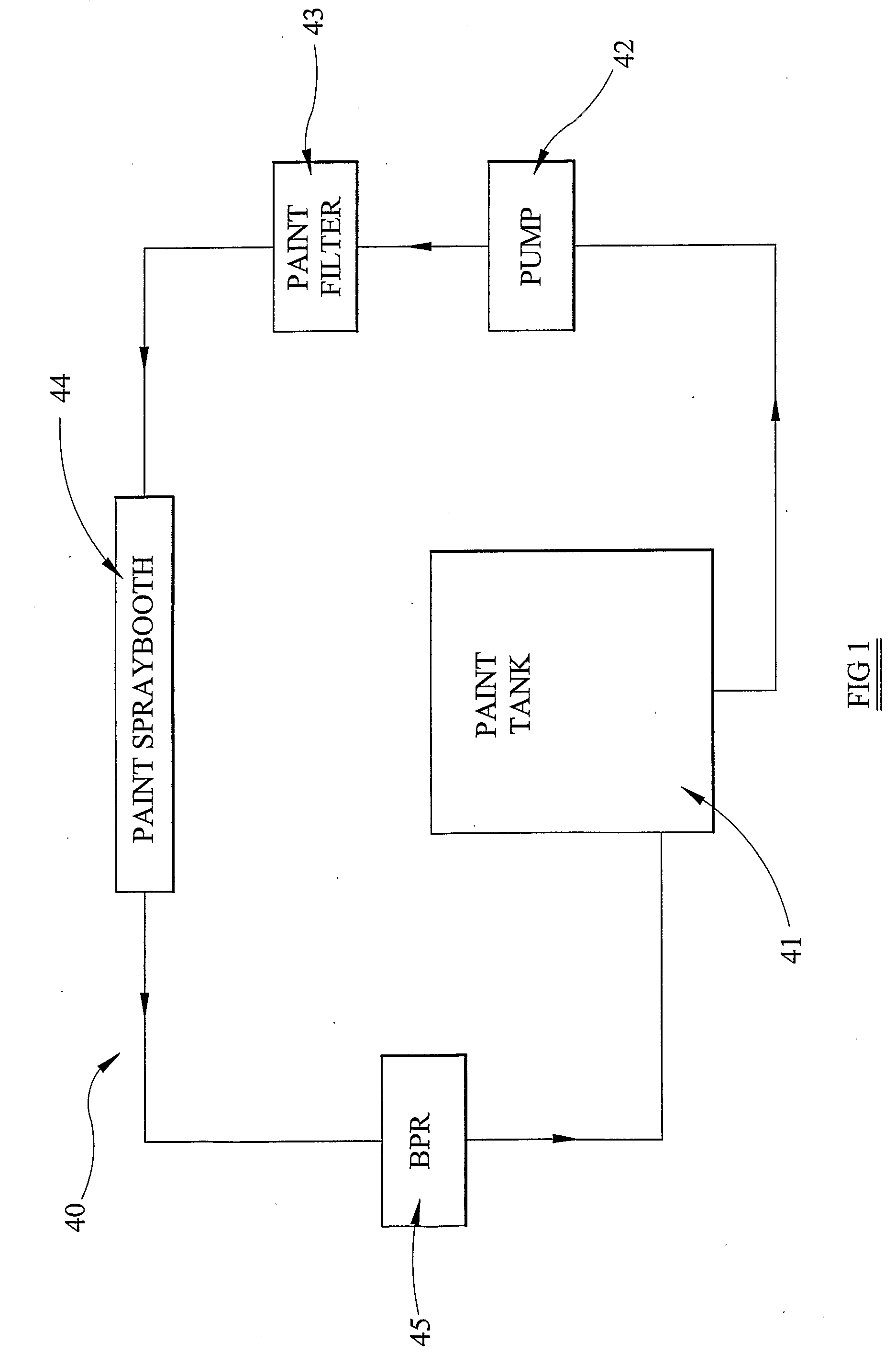
[0021]Referring to the drawings, a paint circulation system 40 employing a BPR 45 is shown in FIG. 1. Thus, a pump 42 is operable to supply paint from a paint tank 41 through a paint filter 43 and into a spray booth 44. Any unused paint is then recycled and returned to the paint tank 41 via a BPR 45.

[0022]In this set-up, the BPR 45 is employed to control the upstream pressure in the system at the desired level, typically 5 to 10 bar when the paint is in use.

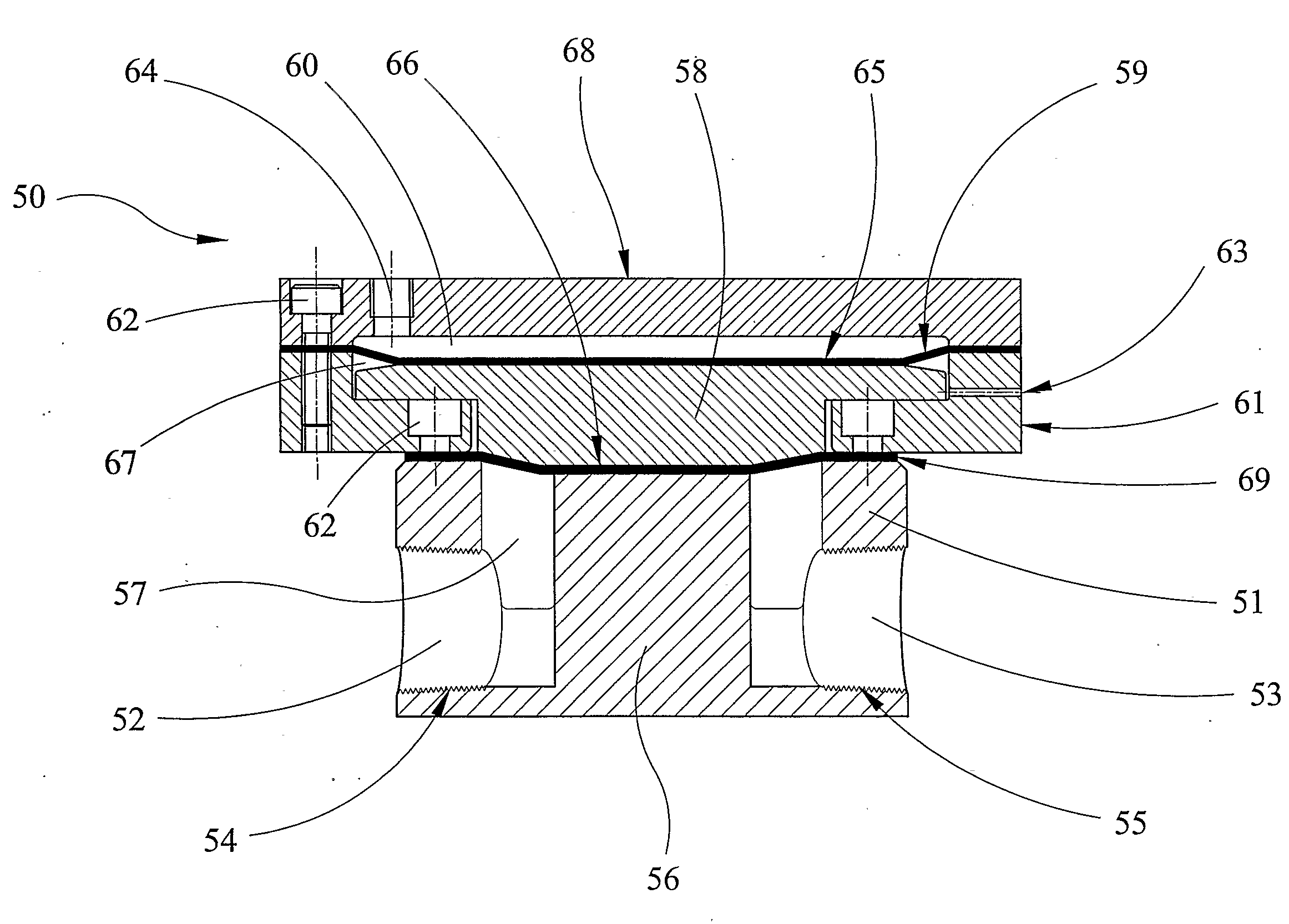
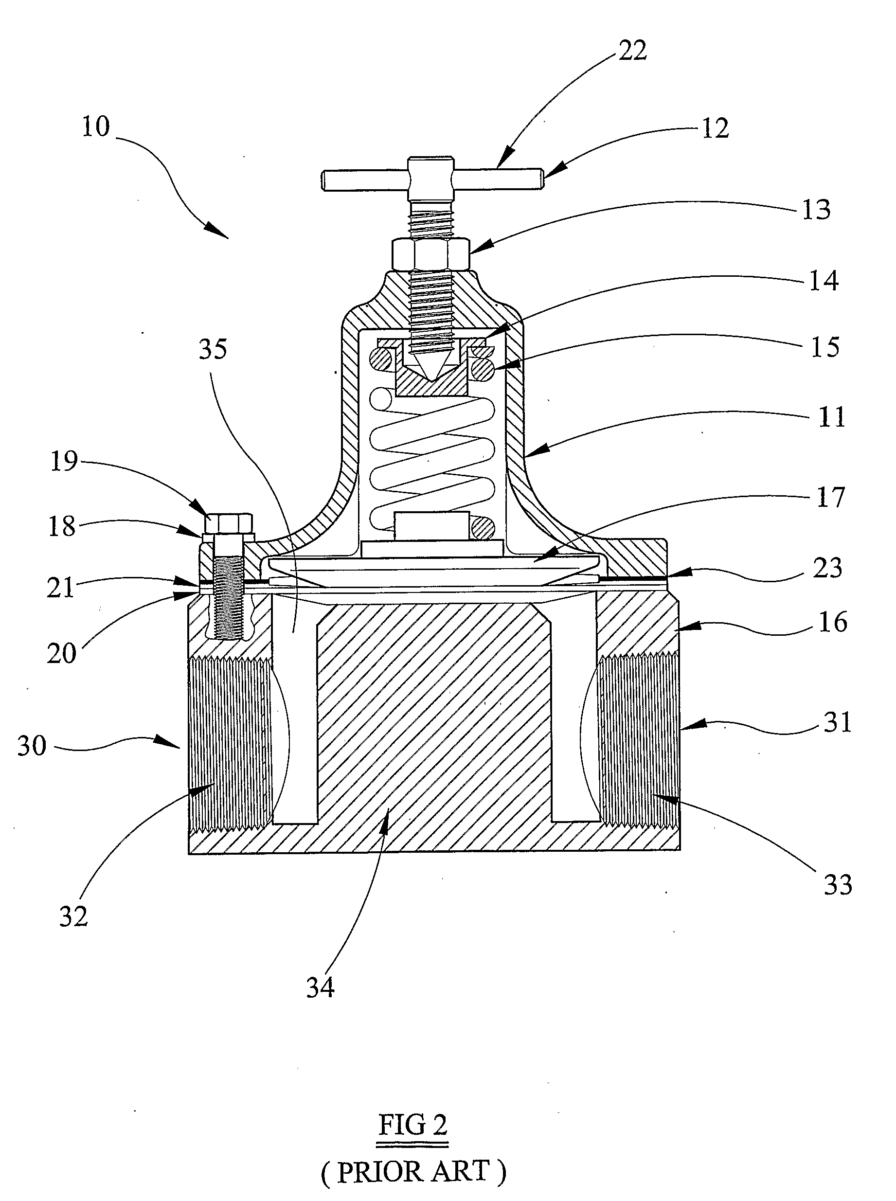
[0023]A prior art back pressure regulator (BPR) 10, for use in a paint circulation system 40, is shown in FIG. 2. This comprises a body portion 16 with an inlet path 30 and an outlet path 31, with respective screw thread couplings 32 and 33 for attachment to respective conduits used in the paint circulation system 40. A structure 34 is disposed between said inlet path 30 and said outlet path 31 to create a constricted flow path 35 there between. A flexible diaphragm 20 is provided to vary the size of the constricted flow path 35 ...


PUM


Abstract

A paint circulating system back pressure regulator comprises a flow passage for paint, at least part of which is disposed between a fixed structure and a moveable surface which is moveable to vary the width of the flow passage so as to regulate a pressure of paint upstream of the regulator. The regulator is also provided with a chamber having an opening for communicating with a supply of a pressurised fluid for controlling operation of the regulator.

Description

TECHNICAL FIELD[0001]This invention relates to a back pressure regulator (BPR) for use in a paint circulating system.BACKGROUND ART[0002]Traditional paint spray systems, of the type employed in car manufacturing, may consist of several (say 30) separate paint lines, each providing a different coloured paint to the spray booth. In general, only one colour is sprayed at any one time so only one line is actively employed at any instance. However, even when not being sprayed, it is necessary to circulate the paint in each line through the system at a minimum velocity to prevent the pigments from separating from the carrier fluid.[0003]To ensure that the paint is at the required pressure for spraying, a BPR is used in combination with the paint pump to regulate and maintain the required fluid back pressure at the spray booth. In traditional systems, the BPR is adjusted manually and uses a coil spring, which is used to maintain the paint pressure upstream of the regulator by controlling t...

Claims


Application Information

Patent Timeline
Patent Type & Authority Applications(United States)
IPC IPC(8): F16K31/12B05B12/08B05B15/12
CPCB05B12/088G05D16/185B05B15/1225B05B9/0423B05B14/40B05B15/58Y10T137/7793Y10T137/7825Y10T137/7826B05B12/08F16K31/385
Inventor SMITH, ALANWOOD, NIGEL C.
Owner CARLISLE FLUID TECH UK LTD
Why Eureka
Try Eureka