Remotely operated production valve and method

a production valve and remote operation technology, applied in the direction of fluid removal, borehole/well accessories, construction, etc., can solve the problem of valves being operated, and achieve the effect of reducing pressure and reducing pressur

Active Publication Date: 2014-03-27
HALLIBURTON ENERGY SERVICES INC
View PDF2 Cites 1 Cited by
  • Summary
  • Abstract
  • Description
  • Claims
  • Application Information

AI Technical Summary

Benefits of technology

[0005]In one aspect, a method of actuating multiple valves in a well is described below. The method can include applying at least one pressure cycle to the valves without causing actuation of any of the valves, and then simultaneously reducing pressure applied to the valves, thereby actuating the valves.
[0006]In another aspect, a method of actuating multiple valves in a well can include applying at least one pressure cycle to the valves without causing actuation of any of the valves; then releasing a locking device of each valve which prevents actuation of each valve; and then reducing pressure applied to the valves, thereby actuating the valves.
[0007]A remotely operated valve for use with a subterranean well is also described below. The valve can include a port which provides for fluid communication between an exterior and an interior of the valve; a closure member which selectively permits and prevents fluid flow through the port, the closure member permits flow through the port in response to a decrease in a pressure differential from the interior to the exterior of the valve; and a locking device which prevents displacement of the closure member, the locking device being released in response to mechanical force applied to the locking device.

Problems solved by technology

However, a conventional pressure-operated valve can also respond to applications of pressure which are not intended for operation of the valve, and so it is possible that the valve can be operated inadvertently.

Method used


Image

  • Remotely operated production valve and method
  • Remotely operated production valve and method
  • Remotely operated production valve and method

Examples


Embodiment Construction

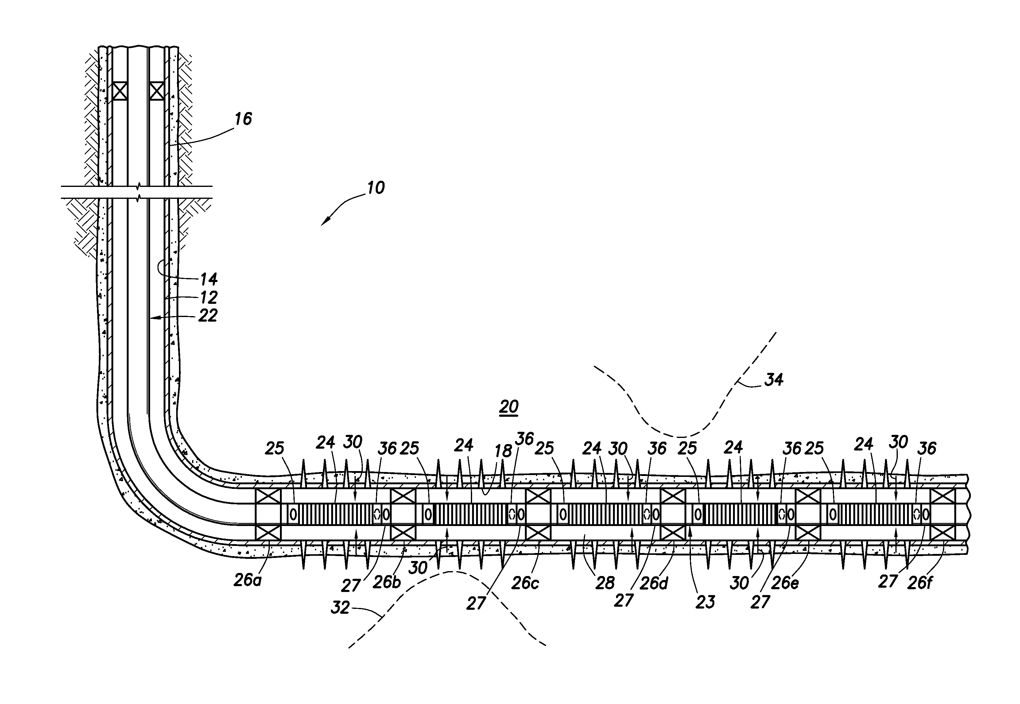
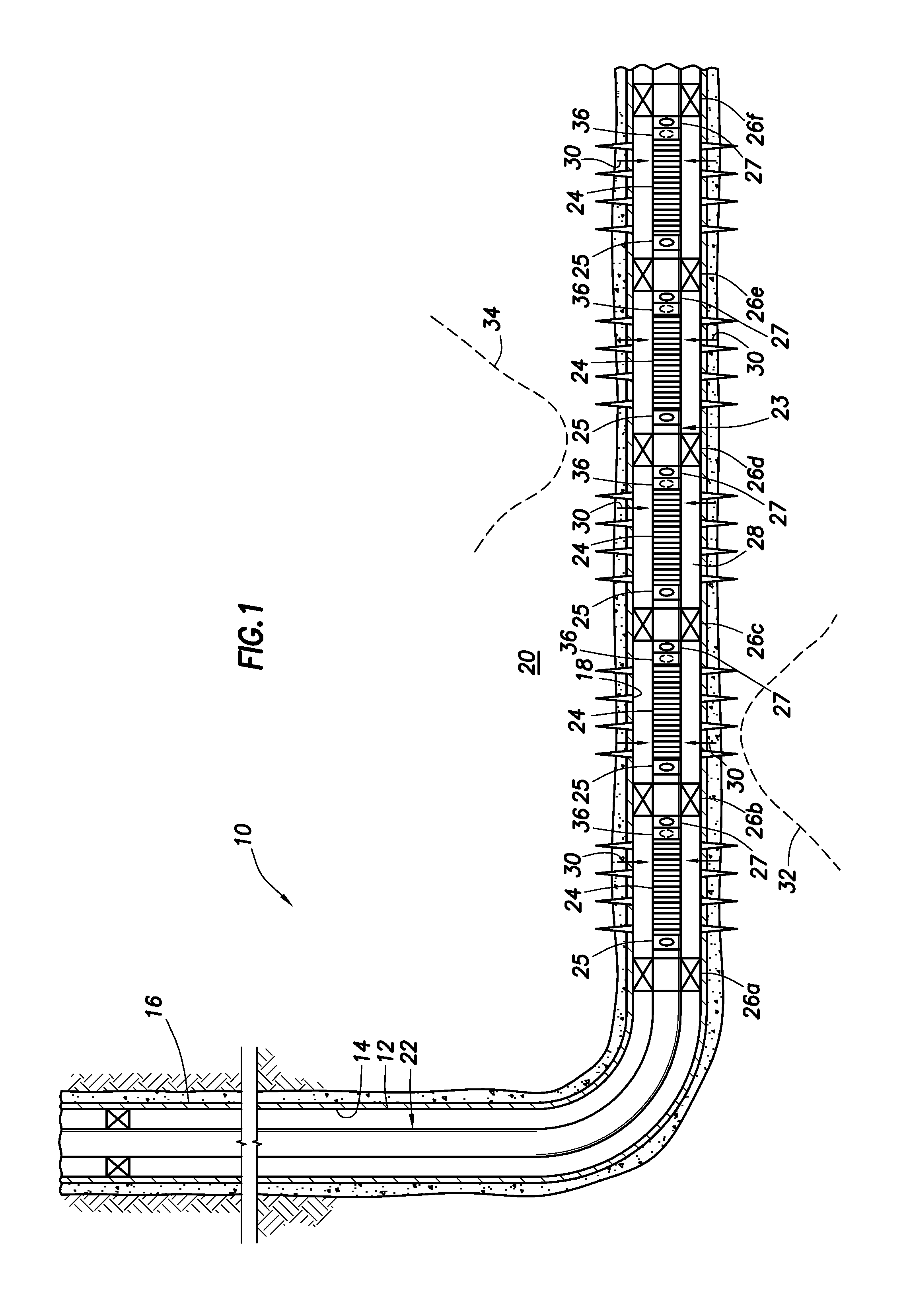
[0014]Representatively illustrated in FIG. 1 is a well system 10 and associated method which can embody principles of this disclosure. In this example, a wellbore 12 has a generally vertical section 14, and a generally horizontal section 18 extending through an earth formation 20.

[0015]A tubular string 22 (such as a production tubing string, or upper completion string) is installed in the wellbore 12. The tubular string 22 is stabbed into a gravel packing packer 26a.

[0016]The packer 26a is part of a generally tubular completion string 23 which also includes multiple well screens 24, valves 25, isolation packers 26b-e, and a sump packer 26f. Valves 27 are also interconnected in the completion string 23.

[0017]The packers 26a-f seal off an annulus 28 formed radially between the tubular string 22 and the wellbore section 18. In this manner, fluids 30 may be produced from multiple intervals or zones of the formation 20 via isolated portions of the annulus 28 between adjacent pairs of th...


PUM


Abstract

A method of actuating multiple valves in a well can include applying a pressure cycle to the valves without causing actuation of any of the valves, and then simultaneously reducing pressure applied to the valves, thereby actuating the valves. Another method can include releasing a locking device of each valve which prevents actuation, and then reducing pressure applied to the valves, thereby actuating the valves. A valve can include a port which provides for fluid communication between an exterior and an interior of the valve, a closure member which selectively permits and prevents fluid flow through the port, the closure member permits flow through the port in response to a decrease in a pressure differential from the interior to the exterior of the valve, and a locking device which prevents displacement of the closure member, the locking device being released in response to mechanical force applied to the locking device.

Description

BACKGROUND[0001]This disclosure relates generally to equipment utilized and procedures performed in conjunction with a subterranean well and, in an example described below, more particularly provides a remotely operated production valve.[0002]Pressure-operated valves used in downhole environments have an advantage, in that they can be operated remotely, that is, without intervention into a well with a wireline, slickline, coiled tubing, etc. However, a conventional pressure-operated valve can also respond to applications of pressure which are not intended for operation of the valve, and so it is possible that the valve can be operated inadvertently.[0003]Therefore, it will be appreciated that it would be desirable to prevent inadvertent operation of a remotely operated valve.SUMMARY[0004]In the disclosure below, a well system, method and valve are provided which bring improvements to the art of operating valves in well environments. One example is described below in which the valve ...

Claims


Application Information

Patent Timeline
Patent Type & Authority Applications(United States)
IPC IPC(8): E21B34/08
CPCE21B34/08E21B2200/06E21B34/102E21B43/04E21B43/14E21B43/26
Inventor WILLIAMSON, JR., JIMMIE R.VICK, JR., JAMES D.
Owner HALLIBURTON ENERGY SERVICES INC
Why Eureka
Try Eureka