Portable, Manually-Guided Implement and Shaft System Therefor

Inactive Publication Date: 2008-10-02
HEINZELMANN GEORGE
View PDF14 Cites 19 Cited by
  • Summary
  • Abstract
  • Description
  • Claims
  • Application Information

AI Technical Summary

Problems solved by technology

A tube made of a fiber composite material can snap and thereby be destroyed already at relatively slight deformations.
To achieve an adequate resistance to snapping, however,

Method used


Image

  • Portable, Manually-Guided Implement and Shaft System Therefor
  • Portable, Manually-Guided Implement and Shaft System Therefor
  • Portable, Manually-Guided Implement and Shaft System Therefor

Examples


Embodiment Construction

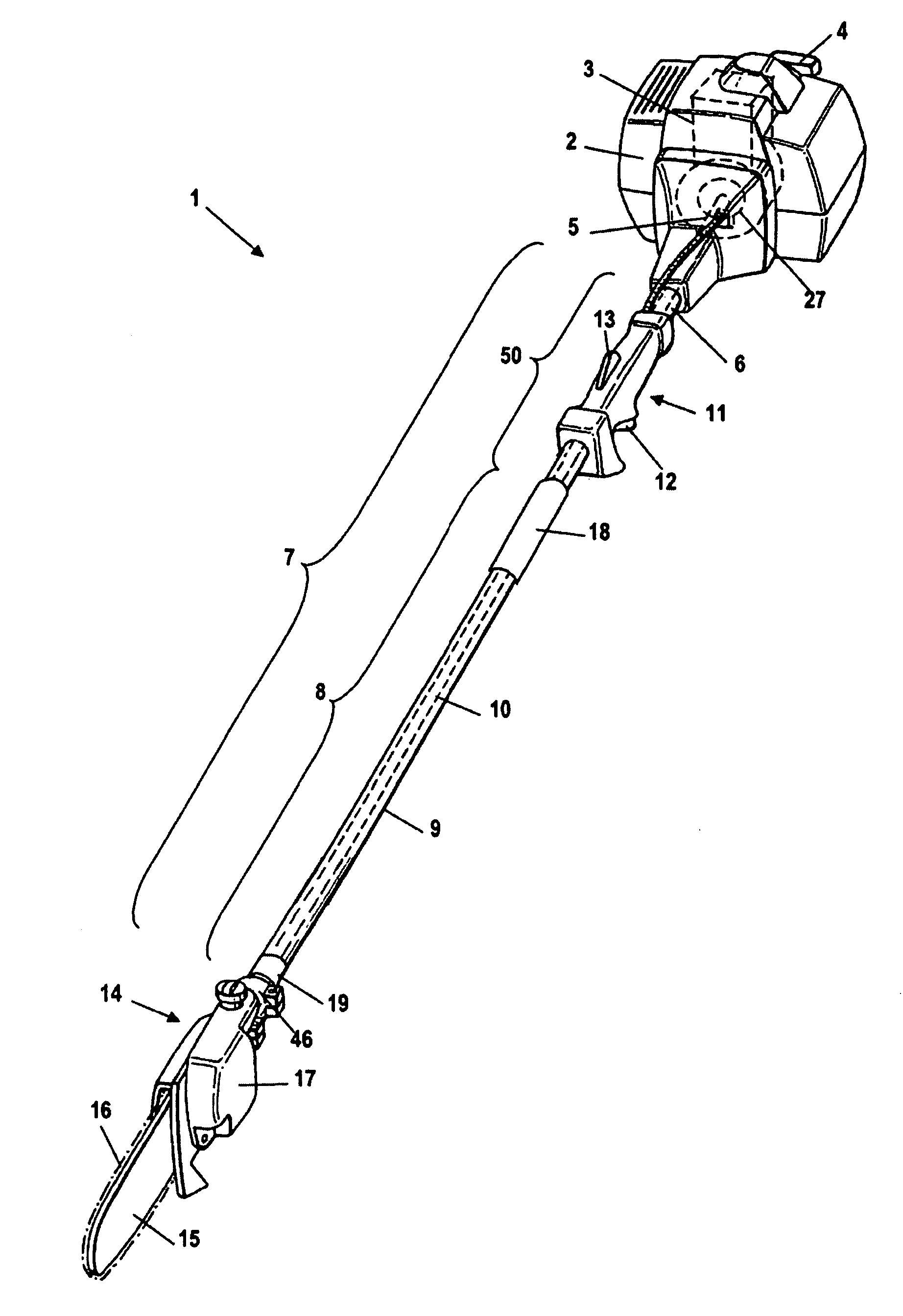
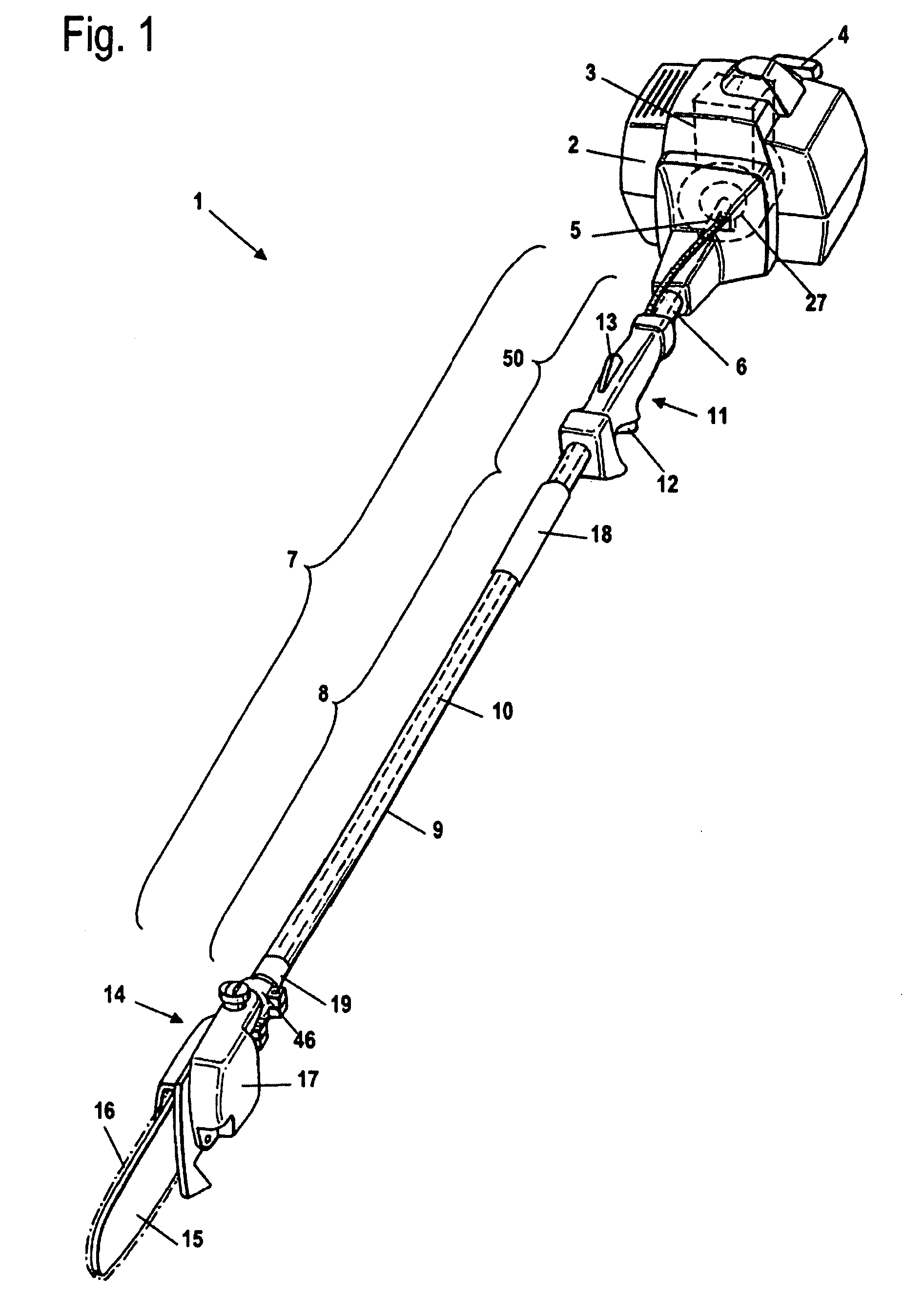
[0044]Referring now to the drawings in detail, the portable, manually-guided implement 1 shown in FIG. 1 is embodied as a pole pruner. The implement 1 has a housing 2 in which is disposed the drive motor 3, which is schematically indicated in FIG. 1 and is embodied as an internal combustion engine. The drive motor 3 is, in particular, a single cylinder motor, advantageously a 2-cycle motor or a mixture-lubricated 4-cycle motor. Extending out of the housing 2 is a starter or pull grip 4 of a starter device for starting the drive motor 3. The drive motor 3 rotatably drives a drive shaft 5, and is coupled to the drive shaft via a coupling or clutch 27.

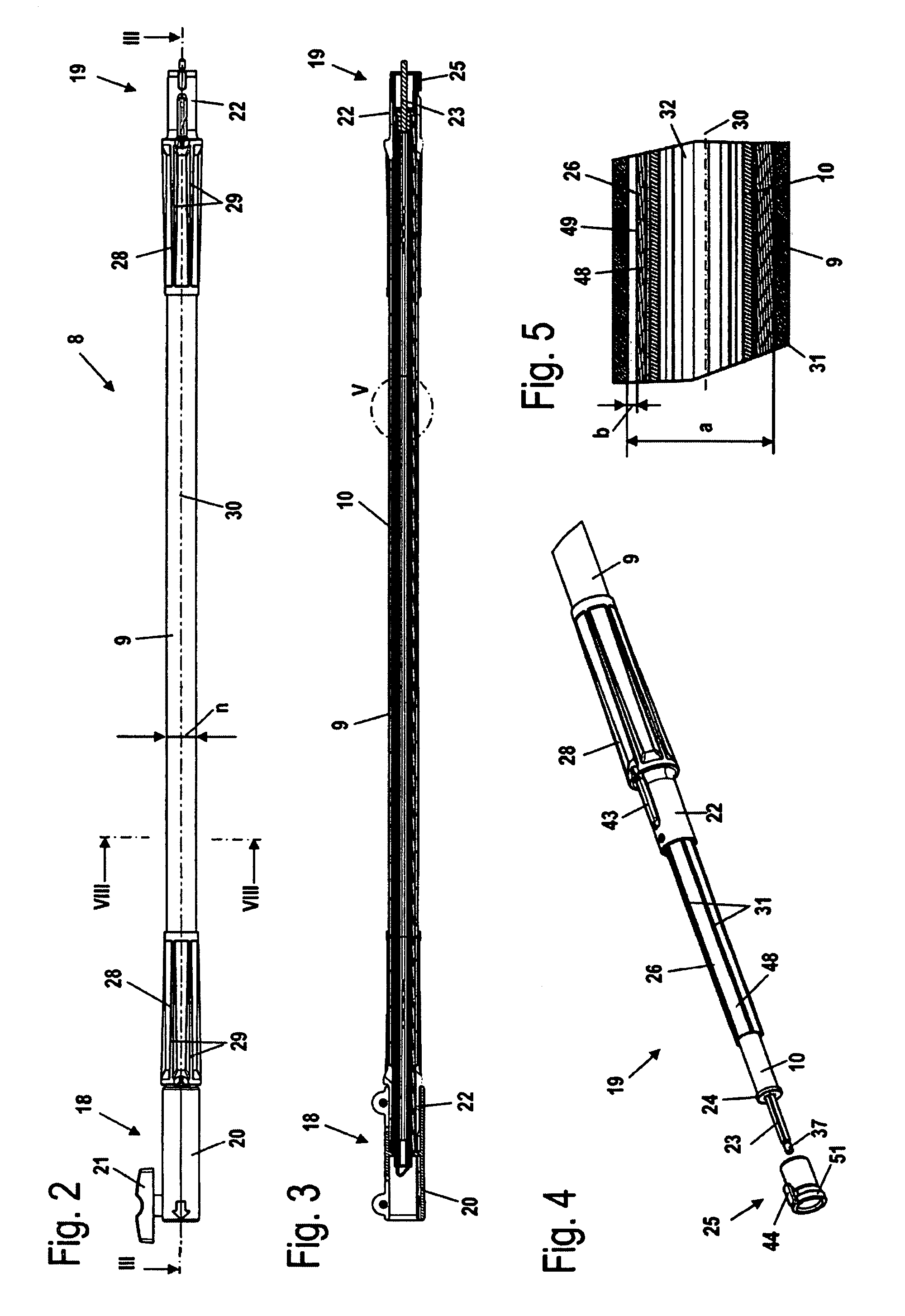
[0045]Secured in position on the housing 2 is a shaft 7 that connects the housing 2 to the gear mechanism housing 14. The shaft 7 includes a guide tube 6, which extends from the housing 2 to the gear mechanism housing 14, as well as the drive shaft 5, which is rotatably mounted in the guide tube 6. Disposed in the gear mechanism housing 1...


PUM


Abstract

A shaft system for a portable, manually-guided implement, including an upper connector and a lower connector for connection to adjoining components. The shaft system has a guide tube portion and a drive shaft portion supported in the guide tube portion by at least one support bushing. The guide tube portion is made of carbon fiber reinforced polymeric material. In at least one region of the periphery of the support bushing a first spacing is formed between the support bushing and the guide tube portion, wherein the first spacing is up to approximately 15% of the inner diameter of the guide tube portion. The shaft system can be utilized with a portable, manually-guided implement.

Description

[0001]The instant application should be granted the priority date of Mar. 31, 2007 the filing date of the corresponding German patent application 10 2007 015 680.6BACKGROUND OF THE INVENTION[0002]The present invention relates to a shaft system for a portable, manually-guided implement and also relates to a portable, manually-guided implement.[0003]US 2003 / 0229993 A1 discloses a tube for a trimmer or a thinning saw, on one end of which is disposed a motor and on the other end of which is disposed the working tool. Disposed in the tube is a bearing that is supported against the outer tube via ribs. The drive shaft is mounted in the bearing. The tube can be made of a fiber composite material.[0004]A tube made of a fiber composite material can snap and thereby be destroyed already at relatively slight deformations. The advantage of a tube made of fiber composite material is the relatively light weight of this material. To achieve an adequate resistance to snapping, however, the thicknes...

Claims


Application Information

Patent Timeline
IPC IPC(8): A01D34/00B26B7/00
CPCA01D34/90
Inventor HEINZELMANN, GEORGE
Owner HEINZELMANN GEORGE
Why Eureka
Try Eureka