
Multi-purpose exhaust valve spring

a technology of exhaust valve and spring, which is applied in the direction of valve housing, valve operating means/release devices, machines/engines, etc., can solve the problem of exhaust gas leaking along the path formed between the shaft and the valve body

Active Publication Date: 2008-10-02
ARVIN TECH INC
View PDF3 Cites 23 Cited by
  • Summary
  • Abstract
  • Description
  • Claims
  • Application Information

AI Technical Summary

Benefits of technology

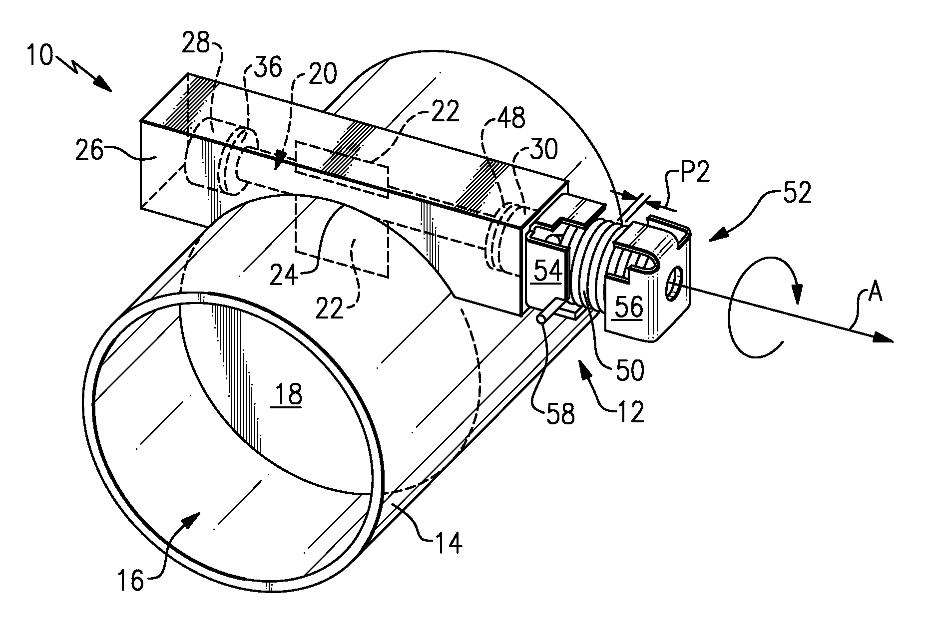
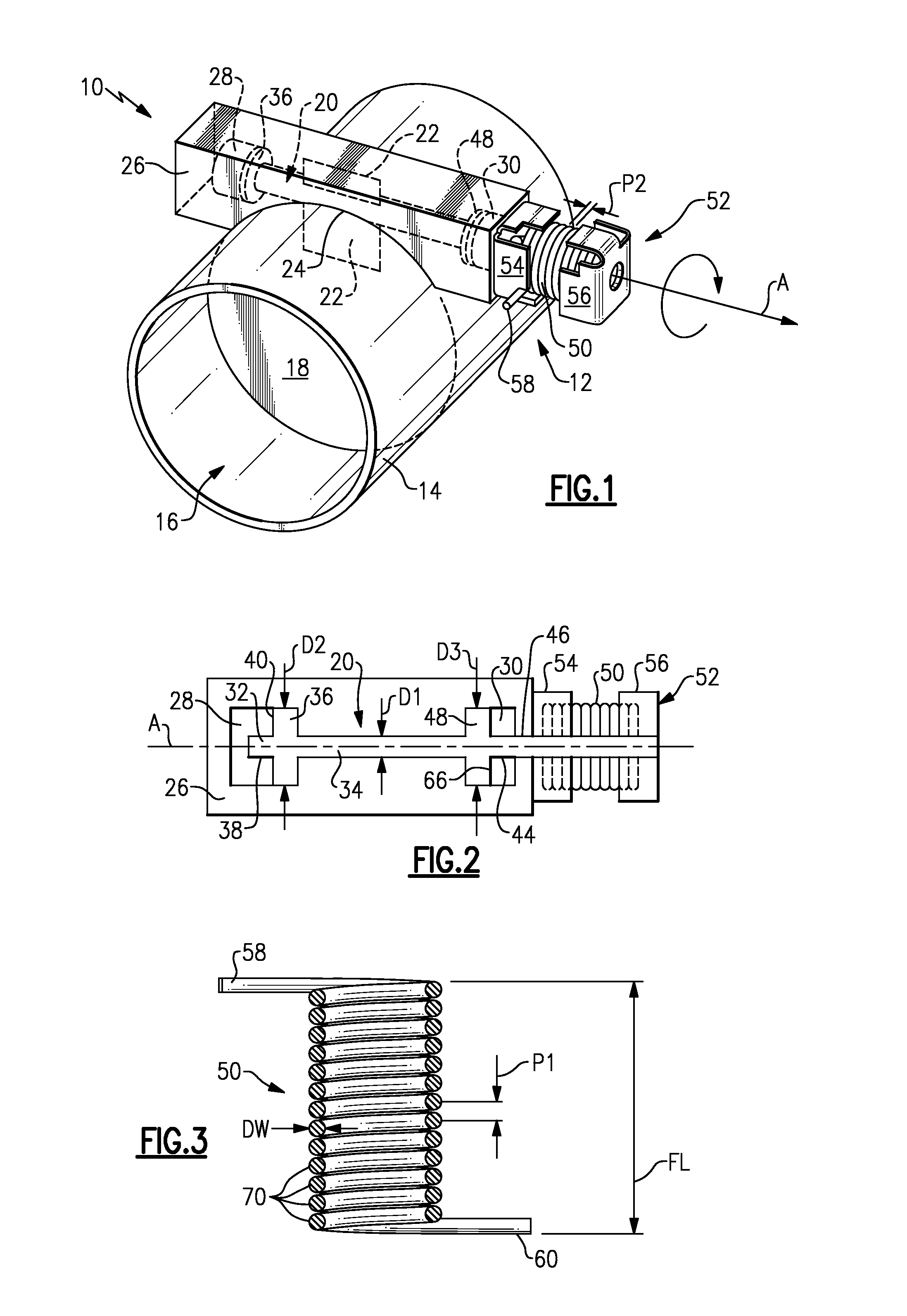
[0005]An exhaust valve includes a valve body that is rotatable with a shaft between open and closed positions. The shaft is rotatably supported by at least one bushing. A single spring is configured to exert both a torsional load and an axial load on the shaft. The torsional load serves to bias the shaft to hold the valve body in a valve closed position. The axial load serves to seal the shaft against the bushing to prevent exhaust gas leakage.
[0007]In the example shown, the shaft is defined by a first diameter and includes a collar portion defined by a second diameter that is greater than the first diameter. When installed, the spring is compressed in an axial direction, which causes the collar portion to seal against an end face of the bushing. This prevents exhaust gas from leaking out between the shaft and the bushing.
[0008]Thus, the subject invention utilizes a single spring to both bias the valve body in a desired operational position and to prevent exhaust gas leakage by sealing the shaft against the supporting bushing.

Problems solved by technology

One disadvantage with this traditional configuration is that exhaust gas can leak along a path formed between the shaft and the bushing.

Method used


Image

  • Multi-purpose exhaust valve spring
  • Multi-purpose exhaust valve spring

Examples


Embodiment Construction

[0013]An exhaust component 10 (FIG. 1) includes an exhaust valve assembly 12 that is movable between an open position and a closed position. In the example shown, the exhaust component 10 comprises a tube body 14 that defines an exhaust gas flow path 16. The exhaust valve assembly 12 includes a valve body 18 that blocks at least a substantial portion of the exhaust gas flow path 16 when in the closed position and is pivoted toward the open position to minimize blockage.

[0014]The valve body 18 is fixed to a shaft 20 with a tang 22. A slot 24 is formed within an outer surface of the tube body 14. A housing 26, shown in this example as a square metal structure, is received within this slot 24 and is welded to the tube body 14. Other housing configurations could also be used. The shaft 20 is rotatably supported within the housing 26 by first 28 and second 30 bushings. In the example shown, the tang 22 comprises a piece of sheet metal that has one portion welded to the shaft 20 and anoth...


PUM


Abstract

An exhaust valve includes a valve body that is fixed for rotation with a shaft supported by at least one bushing. A single spring is used to bias the shaft to hold the valve body in a valve closed position, and to exert an axial load on the shaft to seal the shaft against the bushing to prevent exhaust gas leakage.

Description

TECHNICAL FIELD[0001]The subject invention relates to a spring for an exhaust valve that is configured to exert both torsional and axial loads during installation to hold the exhaust valve in a desired operational position as well as preventing exhaust gas leakage.BACKGROUND OF THE INVENTION[0002]Exhaust valves are used in exhaust components to control exhaust flow rate. Exhaust valves typically include a valve body that is located within an exhaust flow path defined by an exhaust component. The valve body is moveable between a closed position where at least a substantial portion of the exhaust flow path is blocked by the valve body and an open position where blocking of the exhaust flow path is minimized.[0003]The valve body is fixed to a shaft that is supported by bushings. An exhaust valve spring is used to apply a torsional load to the shaft to bias the valve body toward the closed position. One disadvantage with this traditional configuration is that exhaust gas can leak along ...

Claims


Application Information

Patent Timeline
Patent Type & Authority Applications(United States)
IPC IPC(8): F16K31/44
CPCF02D9/04F16K27/0227F16K1/2028F16K1/2007F16K1/2078Y10T137/7898
Inventor ABRAM, KWINKALYANASAMY, GOVINDARAJ
Owner ARVIN TECH INC
Learn More