Sheet-feeding cassette and image forming apparatus

Inactive Publication Date: 2008-10-02
KYOCERA DOCUMENT SOLUTIONS INC
View PDF6 Cites 1 Cited by
  • Summary
  • Abstract
  • Description
  • Claims
  • Application Information

AI Technical Summary

Benefits of technology

[0010]In a case of the sheet-feeding cassette and the image forming apparatus so configured as described above according to an aspect of the present invention, the movable grip portion slides from the projected state of partially projecting from the opening recess of the fixed grip portion to the fitted state of being fitted in the opening recess when the grip portion of the handle is gripped. In accordance with the sliding, the unlocking unit is activated so that the locked portion falls into an unlocked state with respect to the l

Problems solved by technology

Further, there has been a disadvantage that a loud sound occurs when the locking lever

Method used


Image

  • Sheet-feeding cassette and image forming apparatus
  • Sheet-feeding cassette and image forming apparatus
  • Sheet-feeding cassette and image forming apparatus

Examples


first embodiment

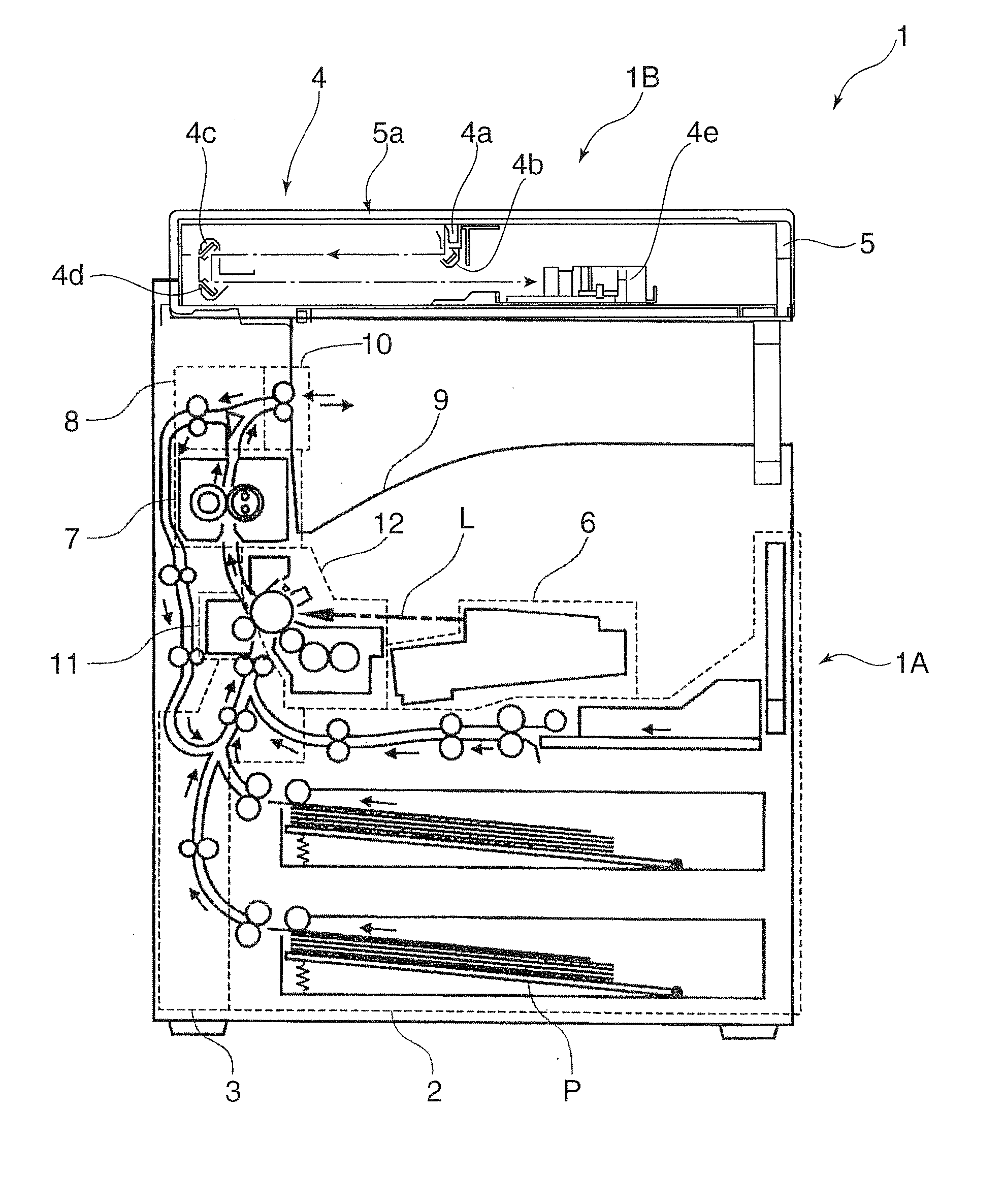
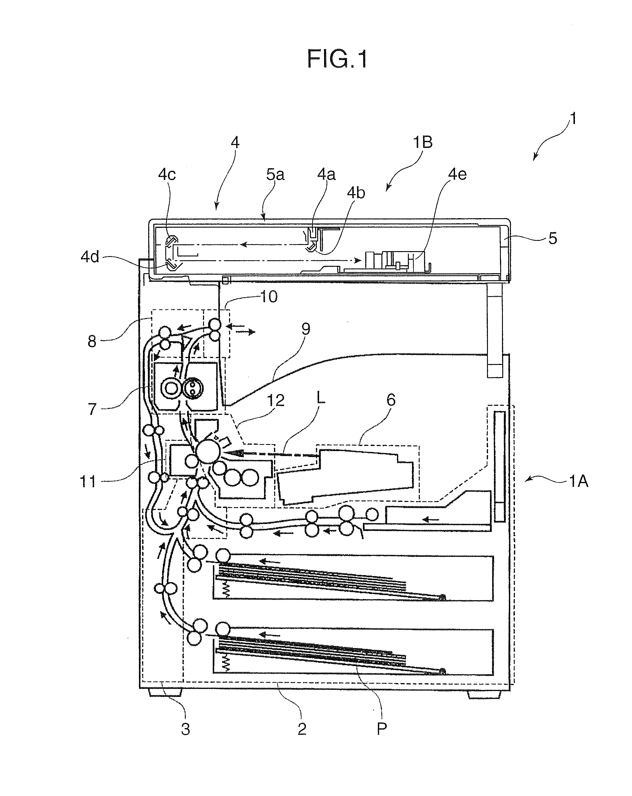
[0032]FIG. 1 is a front sectional view schematically showing an image forming apparatus in accordance with a first embodiment of the present invention. Solid line arrows in the drawing show a conveying path and a convey direction of a sheet, and a one-dotted chain line arrow shows a laser light L.

[0033]An image forming apparatus 1 is provided with an image forming apparatus main body 1A at its lower portion, and an image reading section 1B at its upper portion, and has a basic configuration in which the image forming apparatus main body 1A forms a toner image in accordance with image data read by the image reading section 1B and transfers the toner image onto a sheet P.

[0034]The image forming apparatus main body 1A has a sheet-feeding section 2 at its lower portion. In the sheet-feeding section 2, sheets P such as cut papers before printing are stored in a stack, and the sheets P are separated and sent out one after another.

[0035]In the image forming apparatus main body 1A and on le...

second embodiment

[0065]FIGS. 13 and 14 are sectional views showing a grip portion of a handle in accordance with a second embodiment of the present invention. FIG. 13 shows a state where the grip portion is released. FIG. 14 shows a state where the grip portion is gripped. Other parts have configurations which are the same as those of the first embodiment.

[0066]A grip portion 26A of the second embodiment includes a fixed grip portion 27 having a configuration which is the same as that of the first embodiment, but it includes a movable grip portion 29 having a configuration which is different from that of the movable grip portion 28 of the first embodiment.

[0067]The movable grip portion 29 is different from the movable grip portion 28 of the first embodiment on the following points. In other words, in the movable grip portion 28 of the first embodiment as shown in FIGS. 6 and 7, end portions 28e, 28f which come close to a pair of projecting pieces 27c, 27d arranged across the opening recess 27b of th...

third embodiment

[0070]FIG. 17 is a perspective view showing a grip portion of a handle in accordance with a third embodiment. FIG. 18 shows an opening recess 27b of the grip portion. The portion hatched with lines rising rightward shows a fixed grip portion, and the portion hatched with lines rising leftward shows a movable grip portion. Further, other parts have configuration s which are the same as those of the first embodiment.

[0071]An upper end of an opening recess 27bA of the fixed grip portion 27A is so formed as to be irregular in a direction intersecting a slide direction of the movable grip portion 29A. On the other hand, an upper surface of the movable grip portion 29A is so formed as to be irregular in a direction intersecting the slide direction. A positional relationship of the irregularity is so arranged that the recessed portions in the upper end of the opening recess 27bA correspond to the projecting portions of the upper surface of the movable grip portion 29A, and the projecting p...


PUM


Abstract

A sheet-feeding cassette includes a main body. A locked portion allows the main body to be locked to a locking portion in a cassette accommodating section by inserting the main body in the cassette accommodating section. An unlocking unit is provided for detaching the locked portion from the locking portion when the main body is drawn out of the cassette accommodating section. A handle is provided in the main body and includes fixed and movable grips. The fixed grip has a recess with a “]” shaped cross section open to the insertion direction. The movable grip is slidable to a fitted state in the recess of the fixed grip when the handle is gripped, and a projecting state projecting partially from the recess when gripping is released. The unlocking unit operates for unlocking in accordance with changing of states of the movable grip from the projecting state to the fitted state.

Description

BACKGROUND OF THE INVENTION[0001]1. Field of the Invention[0002]The present invention relates to image forming apparatuses such as a copying machine, a facsimile machine, and a printer and a sheet-feeding cassette for feeding a sheet to such image forming apparatuses.[0003]2. Description of the Related Art[0004]An image forming apparatus like those described above is provided with a locking structure which locks a sheet-feeding cassette when the sheet-feeding cassette is set in a cassette accommodating section of the image forming apparatus, and unlocks the sheet-feeding cassette when the sheet-feeding cassette is drawn out of the cassette accommodating section.[0005]As an example of the locking structure, Japanese Patent Unexamined Publication No. 2006-76695 (hereinafter, referred to as “patent document 1”) discloses a known locking structure which is provided with a locking pin in a cassette accommodating section of an image forming apparatus, a pivotal locking lever locked by the...

Claims


Application Information

Patent Timeline
IPC IPC(8): B65H1/22
CPCB65H1/26B65H2405/121B65H2405/31B65H2801/06B65H1/266
Inventor OHNISHI, YUZO
Owner KYOCERA DOCUMENT SOLUTIONS INC
Why Eureka
Try Eureka