System and method for recording interference fringes in a photosensitive medium

Inactive Publication Date: 2003-04-17
TERAXION
View PDF0 Cites 8 Cited by
  • Summary
  • Abstract
  • Description
  • Claims
  • Application Information

AI Technical Summary

Benefits of technology

[0007] It is therefore an object of the present invention to provide a system and method for recording a long grating into a photosensitive medium that does not require either large collimating optics or high precision feedback electronics.

Problems solved by technology

This method has many drawbacks, especially for the manufacturing of large area gratings (over 50 mm maximum dimension).
Also, a larger beam means larger optics, which are more expensive to obtain in a defect-free form.
Even though noise-free gratings may be made using spatially filtered non-collimated diverging beams, the result usually gives a non-uniform pitch distribution over the grating length.
To write very large gratings (10-20 cm long or more), many large high quality mirrors are needed which may significantly increase the costs of the setup.

Method used


Image

  • System and method for recording interference fringes in a photosensitive medium
  • System and method for recording interference fringes in a photosensitive medium
  • System and method for recording interference fringes in a photosensitive medium

Examples


first embodiment

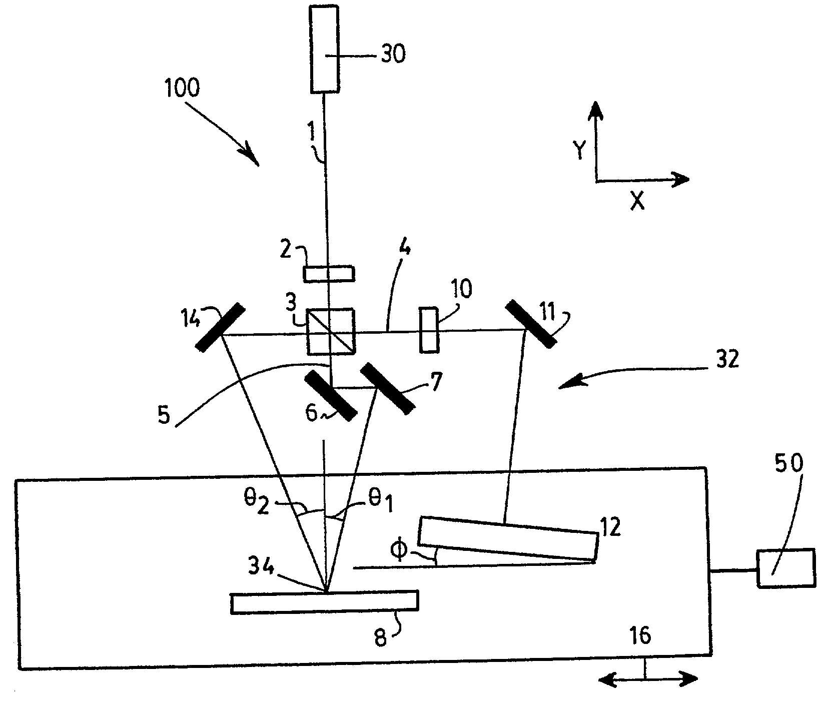
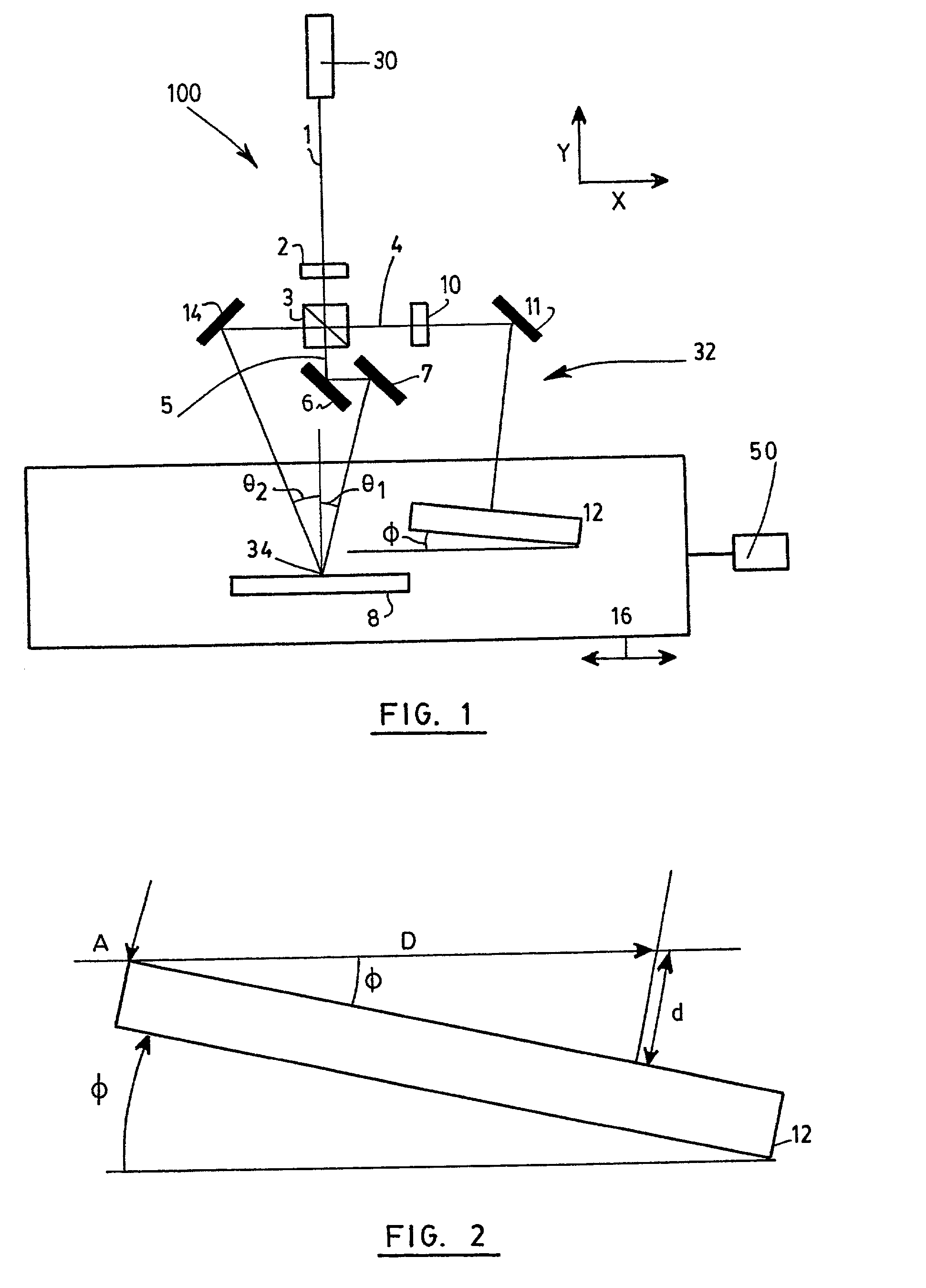
[0021] With reference to FIG. 1, there is shown a system 100 for recording interference fringes in a photosensitive medium 8 according to the present invention. The photosensitive medium 8 is said to extend in a recording plane, which in the illustrated embodiments is defined as the x-z plane. The photosensitive medium may be made of any appropriate material such as optical fiber, photoresist, photopolymer, dichromated gelatin or photosensitive glass.

[0022] The interference fringes are preferably a sinusoidal variation of intensity defining a pattern having a period A calculated by: 1 = sin 1 - sin 2 ,

[0023] where .lambda. is the wavelength of the laser, .theta..sub.1 and .theta..sub.2 are respectively the angles of incidence of both beams 4 and 5 relative the normal of the recording plane (positive clockwise, negative counterclockwise).

[0024] The system 100 first includes light generating means for generating first and second coherent light beams 4 and 5. Preferably, a light source...

third embodiment

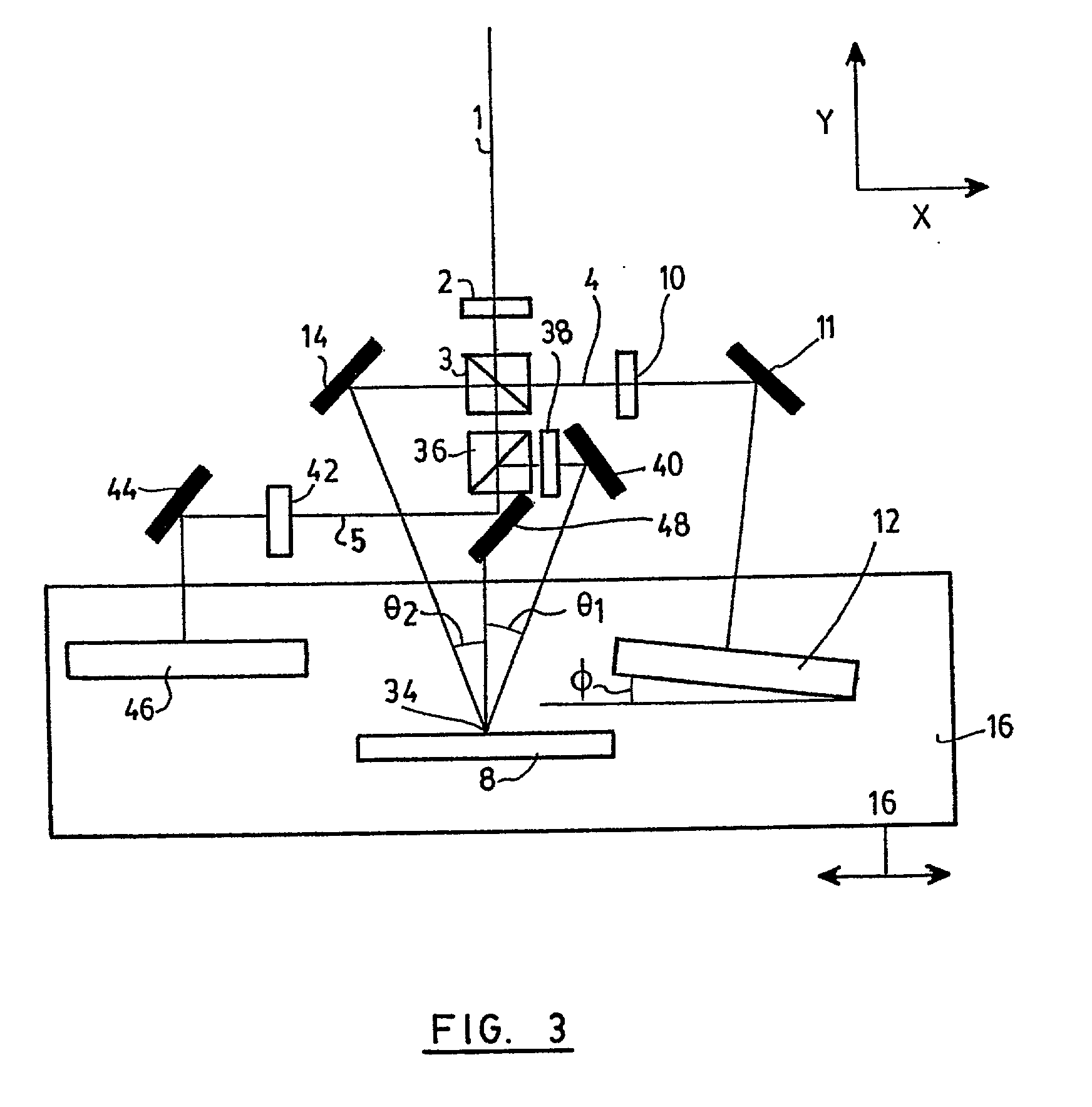
[0042] Referring to FIG. 4, there is shown the present invention similar to the embodiment of FIG. 3. In this new configuration, the stabilizing mirror 46 makes an angle .phi.' with the recording plane. The angle .phi.' is preferably the same as the angle .phi. of the delay mirror 12, but in an opposite direction to maximize the symmetry for both beam paths. In that case, the angles .phi. and .phi.' should both have a value of about half of the value of angle .phi. in the case where the stabilizing mirror 46 is parallel to the recording plane. In this configuration, the system becomes insensitive to a minor Y translation of the stage since both beams are affected in the same way. In addition, it is less sensitive to angular movement in the X-Y plane, since the first light beam 4 impinges on the recording plane by the left side while being reflected by the delay mirror 12 on the right side of the recording plane, while the second light beam 5 impinges on the recording plane by the ri...


PUM


Abstract

A system and a method for recording interference fringes in a photosensitive medium. Two light beams are guided along different light paths to impinge on a photosensitive medium, where they interfere to produce the interference fringes. One of the beam is reflected along its path on a delay mirror forming a fixed angle phi with respect to the plane of the photosensitive medium. Both the photosensitive medium and delay mirror are translated with respect to the light paths of the two beams, thereby recording the interference fringes all along the medium. The angle phi is chosen so that the interference pattern is fixed relative to the photosensitive medium along its length.

Description

[0001] The present invention relates to the recording of interference patterns into photosensitive media, and more particularly concerns an interferometric scanning system and a corresponding method for recording long gratings into such media.[0002] Many optical elements may be fabricated by impinging a light beam onto a photosensitive medium to modify its optical, chemical or mechanical properties. A common application of such a technique is to make diffraction gratings for use in spectroscopic, meteorological and optical communication instruments as well as other types of systems having a use for such diffraction gratings. A very popular type of grating is the fiber Bragg grating used in optical telecommunication systems and devices.[0003] Manufacture of gratings by interferometric methods has been well known for many years. The most common of such methods is by using two generally expanded collimated laser light beams incident on the photosensitive material. After exposure, the p...

Claims


Application Information

Patent Timeline
IPC IPC(8): G02B5/18
CPCG02B5/1857
Inventor TREPANIER, FRANCOIS
Owner TERAXION
Why Eureka
Try Eureka