Power supply circuit

Inactive Publication Date: 2014-01-30
FUNAI ELECTRIC CO LTD
View PDF7 Cites 1 Cited by
  • Summary
  • Abstract
  • Description
  • Claims
  • Application Information

AI Technical Summary

Benefits of technology

The patent text is discussing the problem of fluctuation in the power supplied to a discharge lamp, which can cause flickering. The text describes a power supply circuit that includes a rectifying circuit, a transformer, and a current controller. The current controller adjusts the current flow to the lamp by detecting a voltage signal and a current flow signal. The technical effect of this circuit is that it can suppress fluctuations in power and prevent flickering without making the circuit larger.

Problems solved by technology

Therefore, the discharge lamp may flicker.
However, it has been discovered that a potential problem is the inability to suppress flickering that originates in the fluctuation component of the AC power supply.
However, it has also been discovered that, for fluctuation of the AC power supply to be sufficiently reduced, the capacity of the capacitor ends up being large, which results in a new problem in that the power supply circuit become larger.

Method used


Image

  • Power supply circuit
  • Power supply circuit
  • Power supply circuit

Examples


Embodiment Construction

[0014]A preferred embodiment will now be explained with reference to the drawings. It will be apparent to those skilled in the art from this disclosure that the following descriptions of the embodiment are provided for illustration only and not for the purpose of limiting the invention as defined by the appended claims and their equivalents.

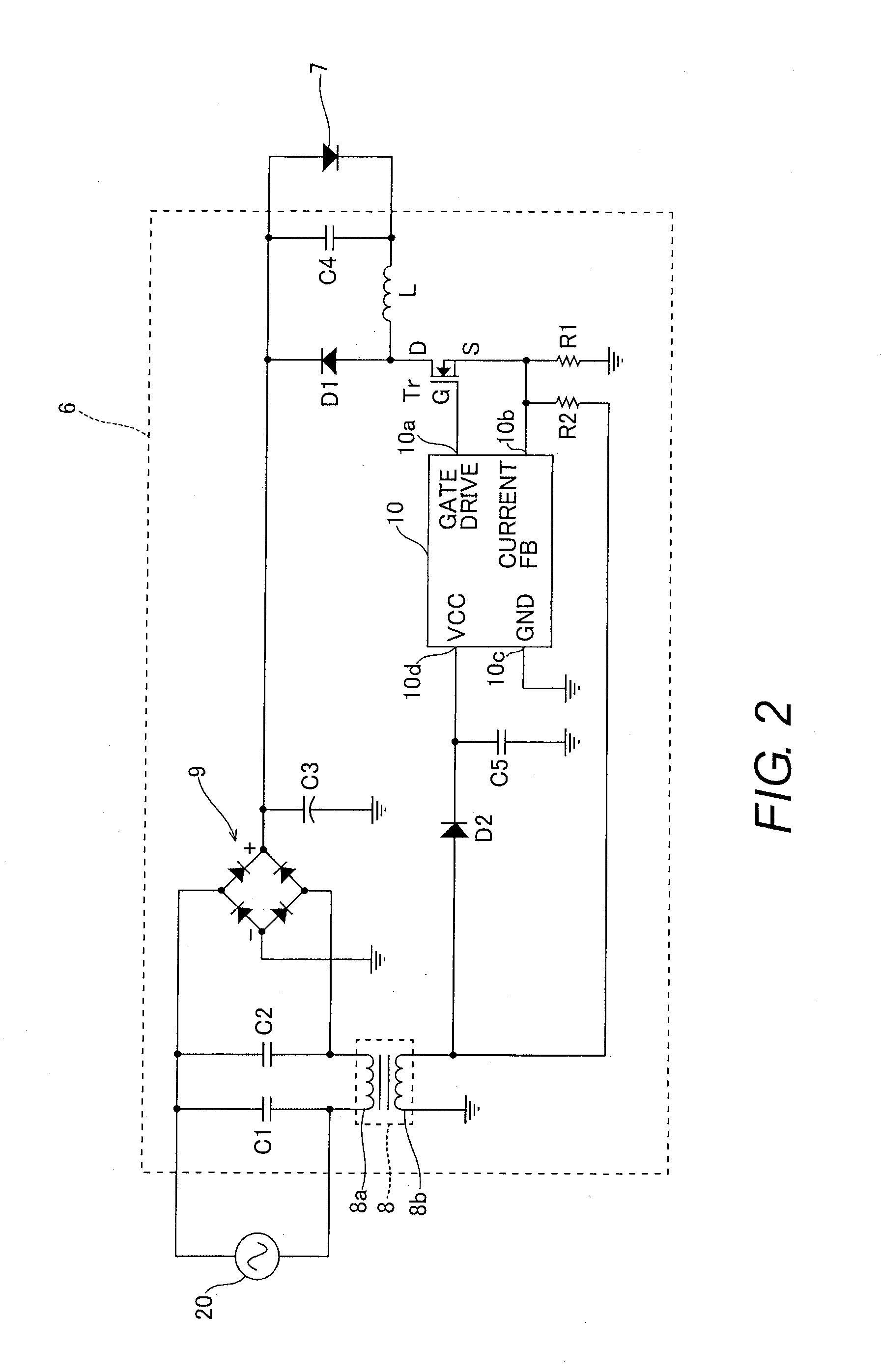
[0015]The configuration of a power supply circuit 6 in accordance with one embodiment will be described through reference to FIGS. 1 and 2.

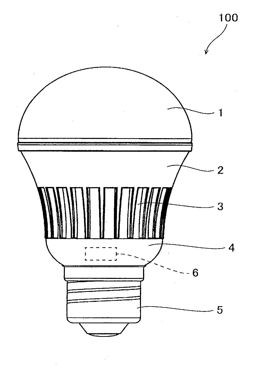
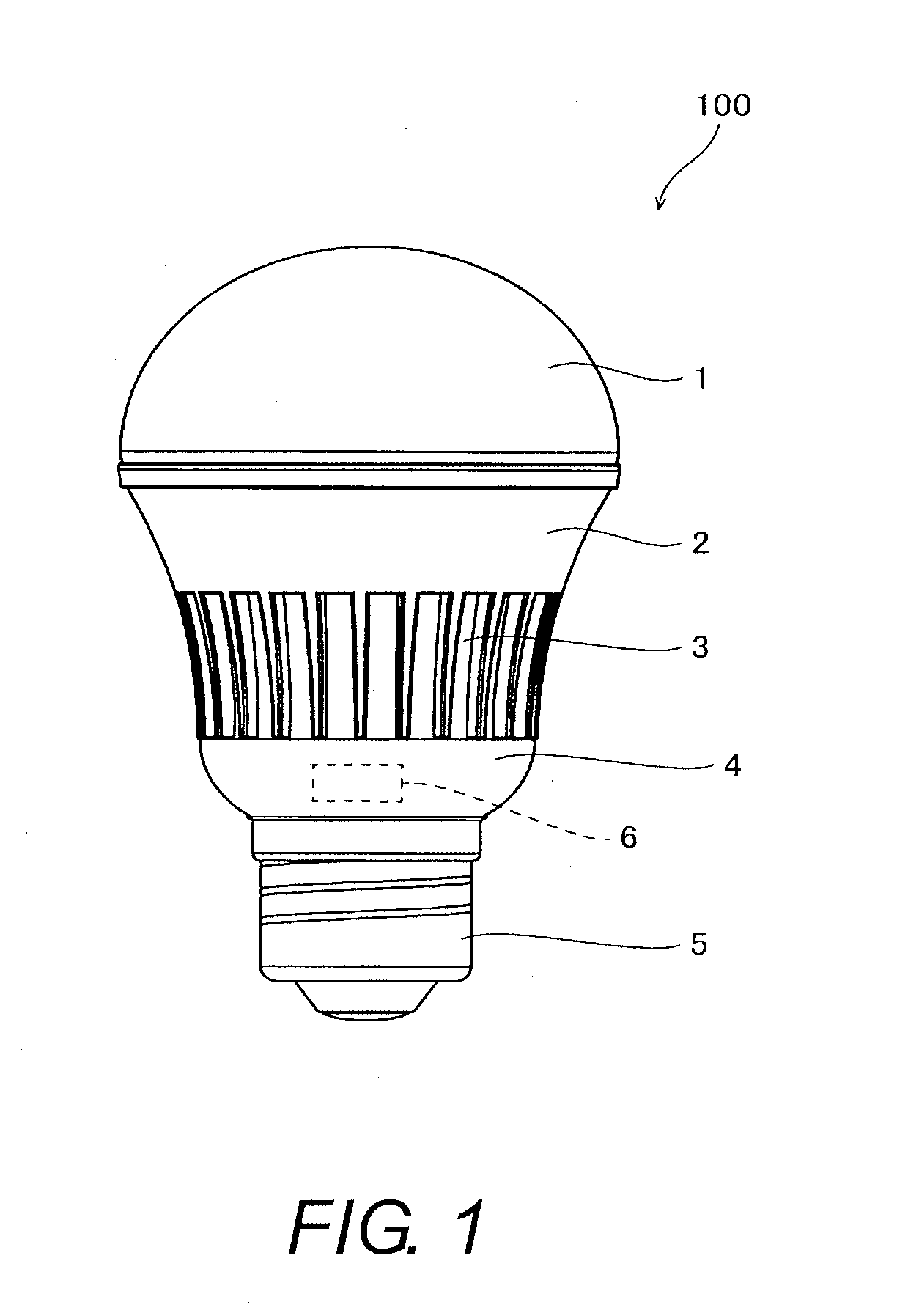
[0016]As shown in FIG. 1, an LED bulb 100 (e.g., illumination device) mainly includes a hemispherical cover lens 1, a heat sink 2, a cylindrical casing 3, a lower cap 4, a socket receiver 5, the power supply circuit 6, and an LED element 7 (see FIG. 2). The LED element 7 is an example of a “light source” of the present disclosure. The power supply circuit 6 is electrically coupled to the LED element 7.

[0017]As shown in FIG. 2, the power supply circuit 6 includes a transformer 8, a rectifying circuit 9, and a c...


PUM


Abstract

A power supply circuit includes a rectifying circuit, a transformer, and a current controller. The rectifying circuit is configured to rectify power of an AC power supply and supply the power to a light source. The transformer is electrically disposed between the AC power supply and the rectifying circuit. The transformer includes a primary winding and an auxiliary winding. The current controller is configured to adjust an amount of current flowing to the light source by detecting a voltage signal of the auxiliary winding and a signal based on the current flowing to the light source.

Description

CROSS-REFERENCE TO RELATED APPLICATIONS[0001]This application claims priority to Japanese Patent Application No. 2012-168712 filed on Jul. 30, 2012. The entire disclosure of Japanese Patent Application No. 2012-168712 is hereby incorporated herein by reference.BACKGROUND[0002]1. Field of the Invention[0003]The present invention generally relates to a power supply circuit. More specifically, the present invention relates to a power supply circuit equipped with a rectifying circuit.[0004]2. Background Information[0005]A power supply circuit equipped with a rectifying circuit was known in the past (see Japanese Laid-Open Patent Application Publication No. 2004-39563 (Patent Literature 1), for example).[0006]The above-mentioned Patent Literature 1 discloses that a discharge lamp device (power supply circuit) includes a rectifying circuit, a power feed circuit, a drive circuit for AC drive of the discharge lamp, a detecting circuit for detecting the current flowing to the discharge lamp,...

Claims


Application Information

Patent Timeline
IPC IPC(8): H05B37/02H05B33/08H05B44/00
CPCH05B33/0824H05B37/02Y02B20/30H05B47/10H05B45/382H05B45/30H05B45/375H05B45/44
Inventor NOBATA, YUKIKAZU
Owner FUNAI ELECTRIC CO LTD
Why Eureka
Try Eureka