
Systems and methods for ornamental variable intensity lighting displays

Inactive Publication Date: 2008-10-02
RSR SALES
View PDF26 Cites 28 Cited by
  • Summary
  • Abstract
  • Description
  • Claims
  • Application Information

AI Technical Summary

Benefits of technology

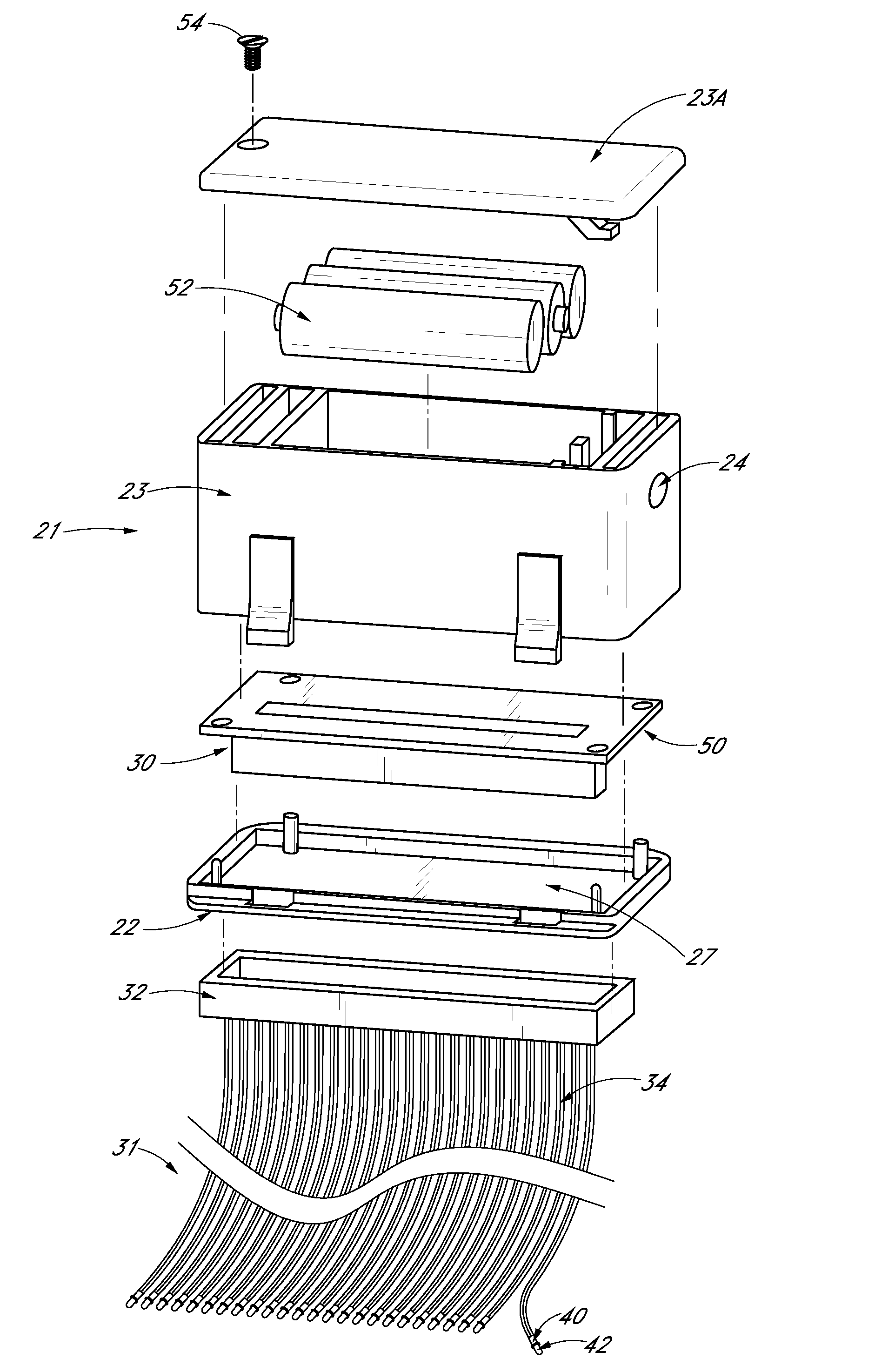
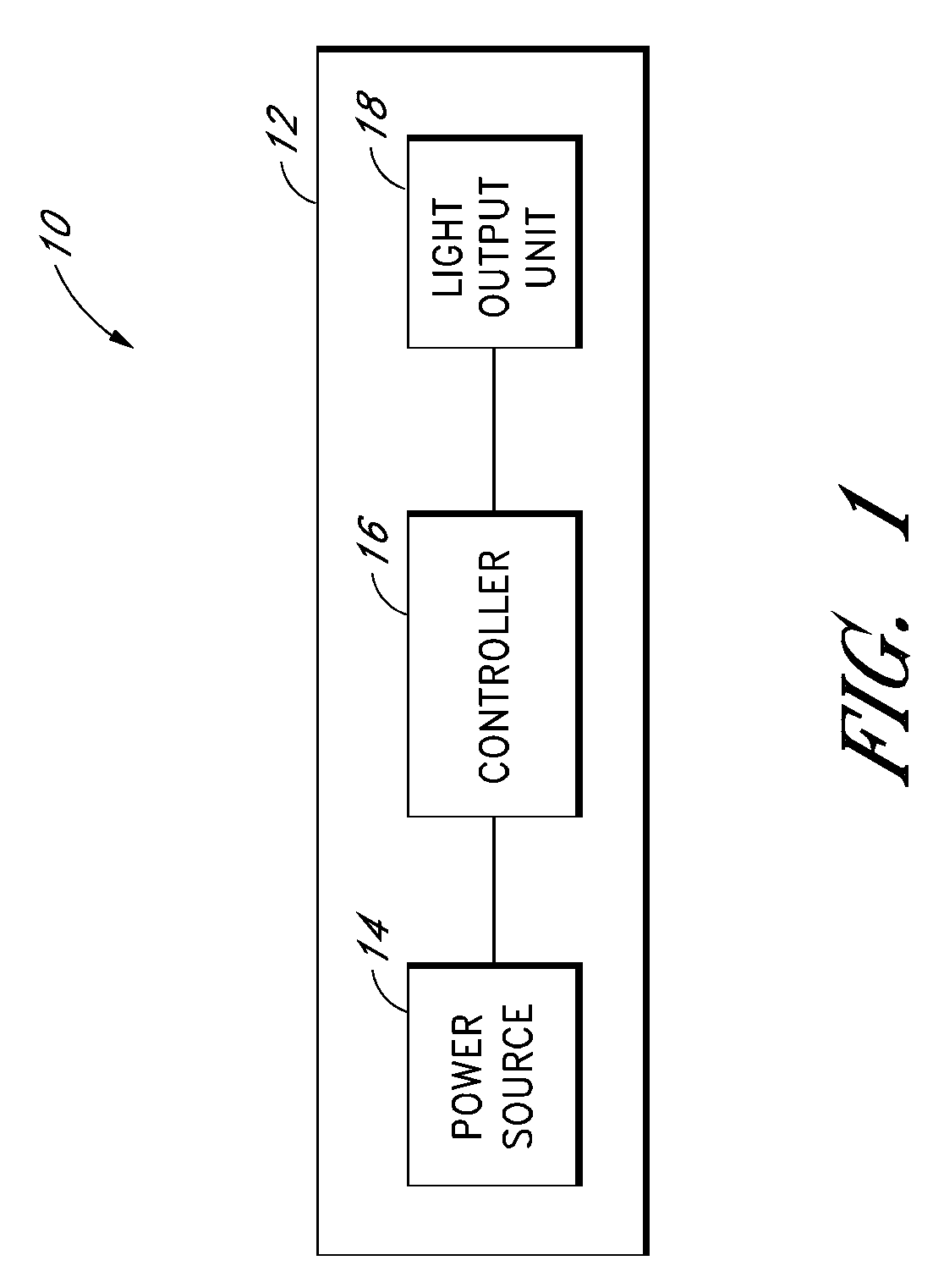
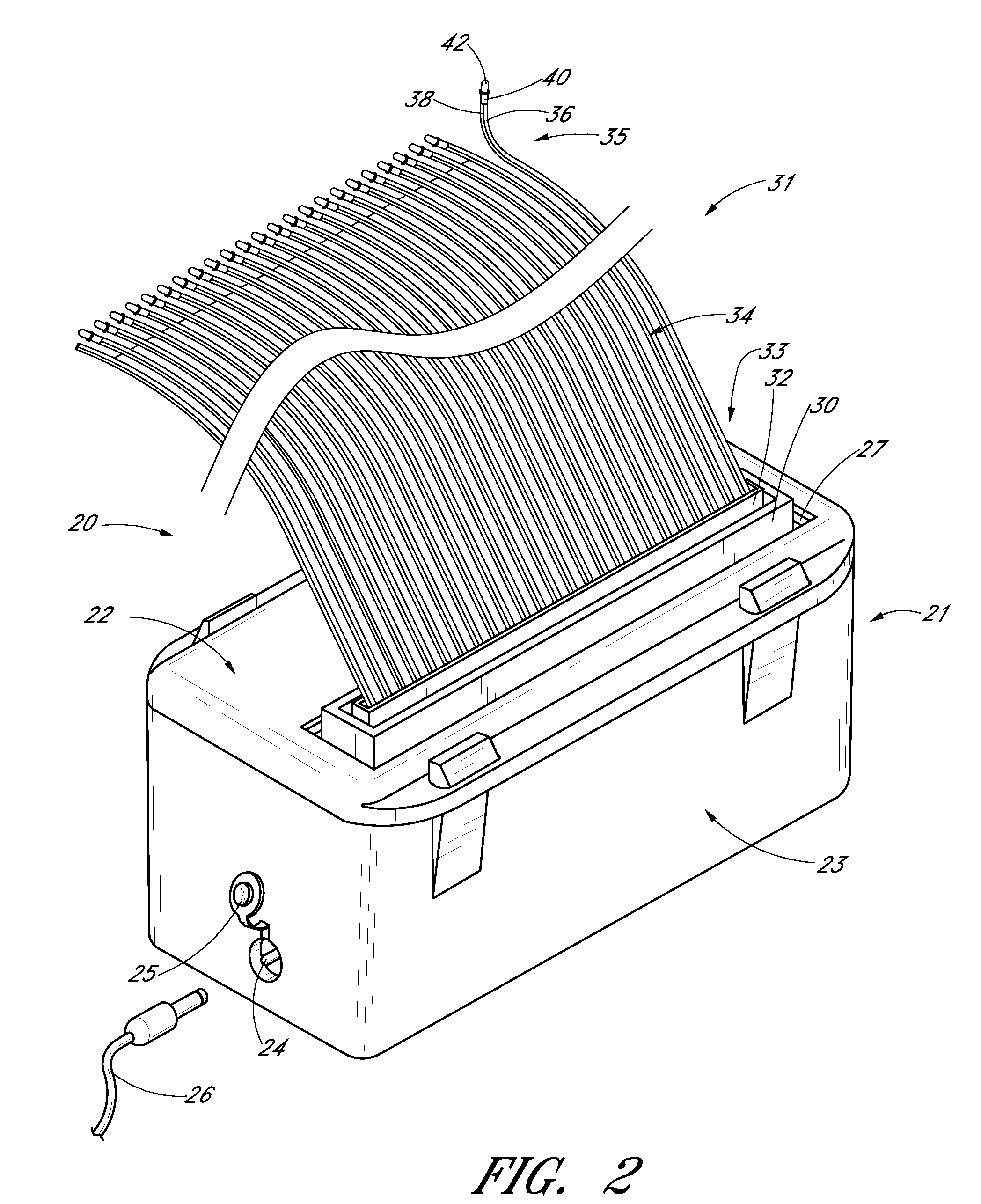
[0006]Accordingly, there is a need for apparatus, systems, and methods that can more cost-effectively produce reliable, realistic variable intensity lighting displays. There is provided in accordance with one embodiment of the present invention an improved lighting display system including a power source, an insulation-displacement connector (IDC), an insulation-displacement connector cable (IDC cable), and at least one light emitter disposed at a distal end of the IDC cable. The IDC is electrically connectable to the power source. The IDC cable is electrically connected to the IDC, and the IDC cable includes a plurality of wires having a distal end. At least one light emitter is disposed at the distal end of each of the wires, with each of the light emitters being electrically connected to the IDC cable.

Problems solved by technology

However, some of the above mentioned lighting systems and other existing lighting systems known in the art have a number of disadvantages in producing variable intensity lighting displays.

Method used


Image

  • Systems and methods for ornamental variable intensity lighting displays
  • Systems and methods for ornamental variable intensity lighting displays
  • Systems and methods for ornamental variable intensity lighting displays

Examples


Embodiment Construction

[0037]As should be understood in view of the following detailed description, this application is primarily directed to apparatuses, systems and methods for producing lighting displays. The apparatuses and systems described herein can be configured to provide a variety of ornamental, functional, static, or dynamic lighting displays for numerous applications and lighting locations. Certain embodiments may be used outdoors or indoors, with landscaping in the midst of plants such as dangling from bushes or trees or arranged in the midst of bouquets and flower arrangements. Various embodiments may be fastened to wires, attached to a mesh, configured to be portable or hand-held, or worn. Some embodiments may be worn or arranged with clothing or accessories, such as in a dress, tiara, halo, hat, hair accessory, belt, pins, shirt, vest, cape, costume or many other arrangements. Some embodiments may be used in greeting cards, books, toys, food, pastries, wedding cakes, birthday cakes, art wo...


PUM


Abstract

A device and method for illuminating an electrically powered decorative lighting system with a plurality of individual light elements that can be positioned in or on surrounding plants, windows, or other display areas to simulate fireflies. The plurality of light emitting elements, such as LEDs or fiber optic cables, are arrangable with mounting devices or can be suspended or attached to any surrounding structure to provide an ornamental lighting effects. Electrical power is provided with rechargeable batteries charged with a solar panel. One preferred embodiment uses insulation-displacement connectors and an insulation-displacement connector ribbon cable to attach the light emitters to a microprocessor control which creates unique and varied timing patterns for the various light emitters to simulate fireflies.

Description

BACKGROUND OF THE INVENTION[0001]1. Field of the Invention[0002]The invention relates generally to the field of ornamental lighting systems, and more specifically to improvements in outdoor decorative landscaping as well as indoor flashing lighting systems with a plurality of lights simulating fireflies, twinkling stars, and other variable lighting pattern displays.[0003]2. Description of the Related Art[0004]Certain lighting systems using wired bulbs, light emitting diodes (LED) and fiber optics to produce ornamental or functional visual effects are known in the art. These lighting systems may be used indoors and outdoors for commercial or personal use in signs, scrolling billboards, and with Christmas, Halloween or other holiday lighting displays. Lighting systems may be used to produce light in varying colors and may provide consistent light, flashing or strobe light effects or patterns. It is also known to use alternating current (AC) or direct current (DC) to provide power to l...

Claims


Application Information

Patent Timeline
IPC IPC(8): H05B37/02
CPCF21S9/037F21S10/005F21V21/0824F21V23/0442F21W2121/00F21Y2101/02H05B33/0842H05B37/029F21Y2115/10H05B47/165H05B47/155H05B45/30H05B45/325
Inventor JAAN, ALBERT
Owner RSR SALES
Learn More