
Work light structure

a technology for working light and structure, applied in fixed installation, lighting and heating apparatus, lighting support devices, etc., can solve the problems of limiting the use of the workshop, the inability of the lamp to light the required area, and the maintenance of the lamp, so as to enhance the versatility of functions and facilitate carrying and storage.

Inactive Publication Date: 2008-10-02
CHIEN CHAO CHUAN
View PDF7 Cites 26 Cited by
  • Summary
  • Abstract
  • Description
  • Claims
  • Application Information

AI Technical Summary

Benefits of technology

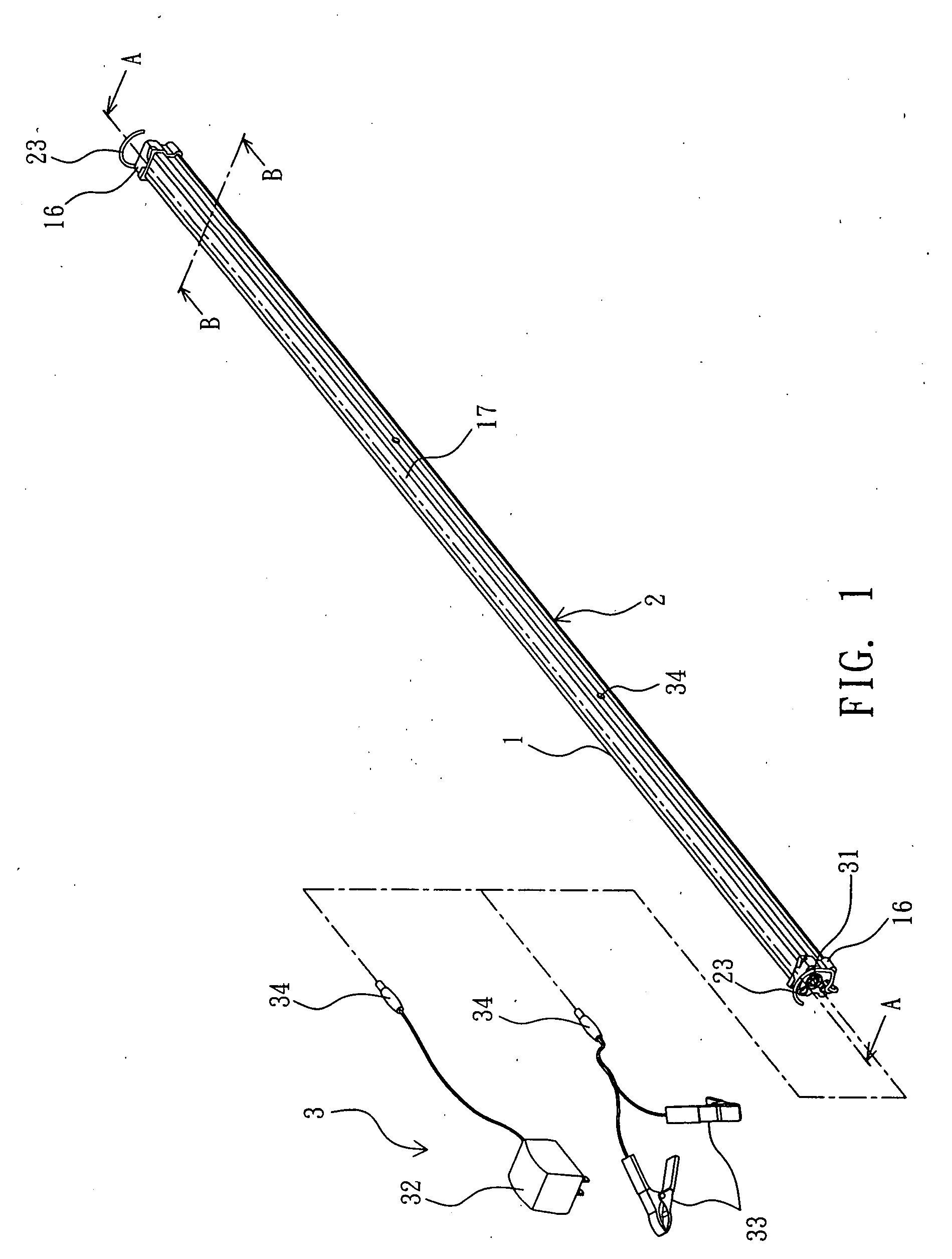
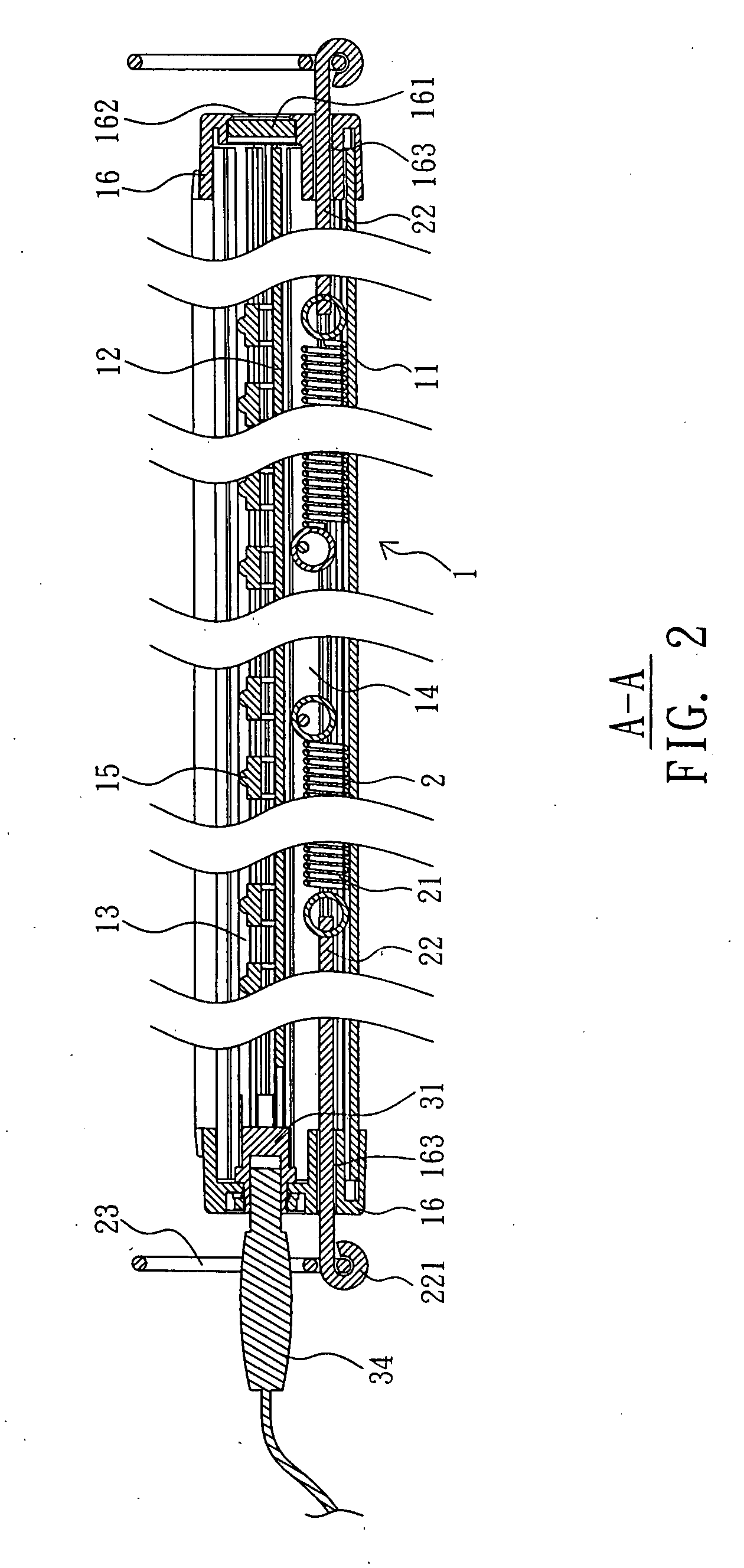
[0006]An object of the present invention is to provide a work light structure whose extension device is enclosedly accommodated and thus concealed in the accommodating portion of the housing and thus when extending or retracting, the resilient component will not be hindered by foreign objects; with the extension and retraction of the resilient component, the two hooks on either end can easily and quickly hook onto a connecting object and the work light structure can be positioned thereon.
[0008]The other object of the present invention is to provide a work light structure with folding and extending functions, which is conducive to carrying away and storage, in particular being stored in a car trunk without taking up too much space. Further, the work light structure in accordance with the present invention after folding can be connected onto a tripod to become a stand light, thereby enhancing the versatile functions of the present invention.

Problems solved by technology

For a car maintenance workshop, for example, the lamps on the workshop usually do not satisfy the need of the maintenance work since the car body or cover, an engine hood or a trunk cover for example, may obstruct the light coming from the lamps on top, and thus the lamps cannot light the area required.
Although the conventional work light can provide the lighting at the maintenance work area, it can only provide lighting to a restricted area due to its dimension.
Also, the light provided by the conventional work light is yellow light, which cannot provide the required area and strength of illumination.
Although the slide-rail work light may provide white light for a larger area of illumination, one of its drawbacks is that since the height of the light source module, the ring body, and the slide rail is relatively large, the work light is not useful if the maintenance space is restricted.
Furthermore, the connection procedure for connecting the work light and the connecting object is tedious and complicated, which requires positioning as well as fixing.
The design of such a work light is thus defective and demands improvements.

Method used


Image

  • Work light structure
  • Work light structure
  • Work light structure

Examples


Embodiment Construction

[0025]With reference to FIGS. 1 to 3, a work light according to the present invention comprises a light source module 1 and an extension device 2, wherein the light source module 1 comprises a long slender housing 11 formed by extruding of aluminum or injection molding of plastics, for example, and laterally connected a printed circuit board 12 which is also a shape of long slender such that the housing 11 is partitioned into a lighting portion 13 and an accommodating portion 14. The printed circuit board 12 is coupled with a plurality of light emitting diodes (LEDs) 15 arranged in line inside the lighting portion 13, and the accommodating portion 14 is reserved for the extension device 2 described later. When the light source module 1 is assembled, each of the two ends of the housing 11 is connected with an end cap 16, respectively, for capping the ends, wherein one of the end caps 16 is disposed with a power supply device 3, a battery for example, for supplying power to enable the...


PUM


Abstract

A work light structure according to the present invention comprises: a light source module having a long slender housing laterally and inwardly connected with a printed circuit board so as to partition the housing into a lighting portion and an accommodating portion, the printed circuit board being coupled with a plurality of light emitting diodes (LEDs) arranged in line inside the lighting portion and each of the two ends of the housing is connected with an end cap, respectively, for capping the ends, and one of the end caps is disposed with a power supply device; an extension device disposed in the accommodating portion and formed by connecting at least a resilient component with its two ends onto a connecting rod, respectively, whose external end is inserted through a rod hole at the end cap and is connected with an externally protruding hook; the two hooks are hooked onto two ends of a connecting object to extend the resilient component, such that the power supply device may provide power to the printed circuit hoard to light up the LEDs.

Description

FIELD OF THE INVENTION[0001]The present invention relates to a work light structure and in particular to a work light structure in which its light source module is disposed with an extension device with its two ends connected with a hook, respectively, to be hooked onto two sides of a connecting object. Further, the present invention provides a foldable work light structure to significantly reduce its length which is conducive to carrying away and storage.BACKGROUND OF THE INVENTION[0002]Lamp has a variety of forms to suit its usage, floor lamp, wall lamp, table lamp, desk lamp, and many others. To meet the demand of a working site, the design of a lamp usually requires specific functions. For a car maintenance workshop, for example, the lamps on the workshop usually do not satisfy the need of the maintenance work since the car body or cover, an engine hood or a trunk cover for example, may obstruct the light coming from the lamps on top, and thus the lamps cannot light the area req...

Claims


Application Information

Patent Timeline
Patent Type & Authority Applications(United States)
IPC IPC(8): F21V21/00
CPCF21L14/02F21Y2101/02F21Y2115/10
Inventor CHIEN, CHAO CHUAN
Owner CHIEN CHAO CHUAN
Learn More