Apparatus diagnosing method, apparatus diagnosis module, and apparatus mounted with apparatus diagnosis module

a technology of diagnosis module and diagnostic method, which is applied in error detection/correction, speed/acceleration/shock measurement device testing/calibration, instruments, etc., can solve the problems of difficult to establish temporal consistency and difficult to specify an environmen

Inactive Publication Date: 2008-10-02
HITACHI LTD
View PDF5 Cites 59 Cited by
  • Summary
  • Abstract
  • Description
  • Claims
  • Application Information

AI Technical Summary

Benefits of technology

[0012]Accordingly, an object of the present invention is to provide an apparatus diagnosing method and an apparatus diagnosis module in which data about an operational environment corresponding to the intermittent error caused by change in the operational environment of an apparatus is collected by the sensor in association with error information generated in the apparatus, and therefore the environment factor causing the intermittent error can be readily specified.
[0019]In addition, according to the present invention, since the sensor data can be collected only for limited time periods before and after the error occurrence, a small-sized / capacity memory can be adopted as a memory for sensor data collection mounted on each control board in an apparatus. Therefore, it is possible to achieve the reduction in size of the control board and to apply the apparatus diagnosing method to various control boards. Further, the number of the sensors for acquiring data can be increased by memory expansion, so that a detailed analysis of the intermittent error can be made possible for each control board.

Problems solved by technology

Therefore, even if the control board 2 on which the error has occurred can be specified, it may be difficult to establish temporal consistency between an error occurrence time and the sensor data 3a collected in real time, so that it is difficult to specify an environmental factor that causes the error.

Method used


Image

  • Apparatus diagnosing method, apparatus diagnosis module, and apparatus mounted with apparatus diagnosis module
  • Apparatus diagnosing method, apparatus diagnosis module, and apparatus mounted with apparatus diagnosis module
  • Apparatus diagnosing method, apparatus diagnosis module, and apparatus mounted with apparatus diagnosis module

Examples


first embodiment

[0049]A system applying an apparatus diagnosing method which is a first embodiment of the present invention will be explained below with reference to FIGS. 1 to 7.

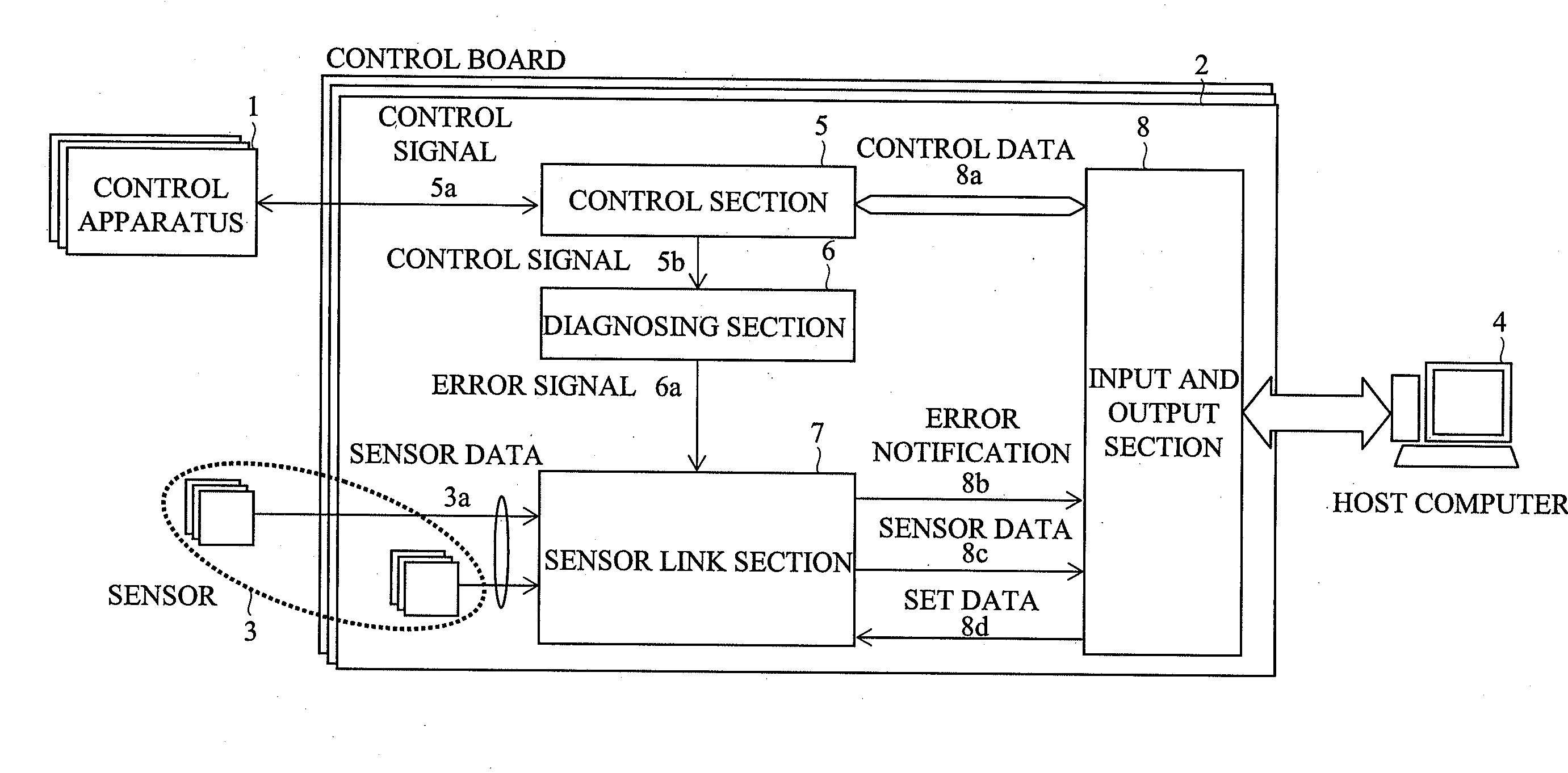
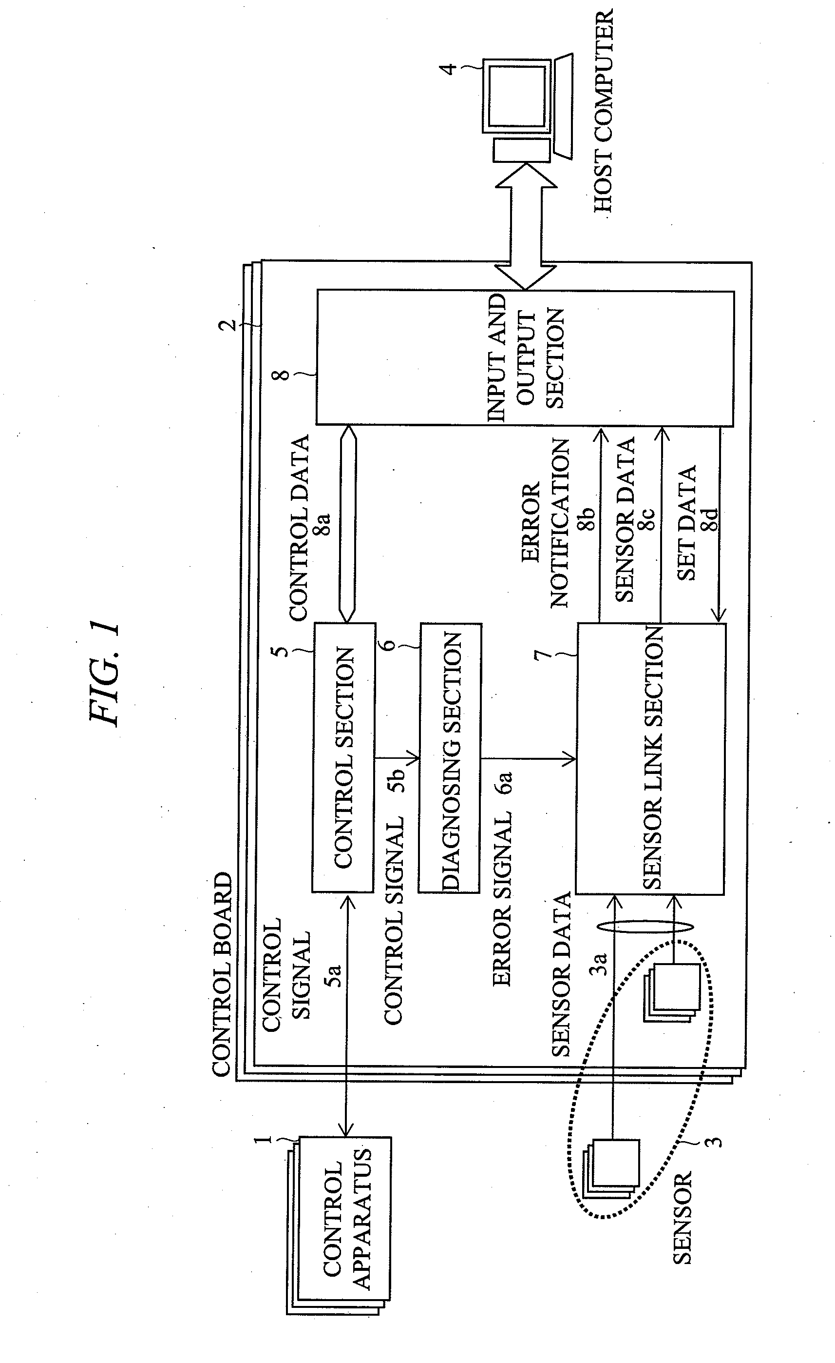
[0050]FIG. 1 is a diagram showing an entire configuration of a system according to the embodiment. The system includes: the control apparatuses 1 such as a motor, a pump, or an operation panel; the control boards 2 to control the control apparatus 1; the sensors 3 which are disposed around the control apparatuses 1 or the control boards 2, or mounted on the control boards 2 to measure data about the operation environments of the control apparatuses 1 and the control boards 2; and the host computer 4 serving as a control system which sets a control procedure, an operation mode, and the like to the control boards 2, and which collects error information of each control board 2 and the sensor data 3a from the sensors 3.

[0051]The control board 2 includes: the control section 5; the diagnosing section 6 which diagnoses an operat...

second embodiment

[0082]A system applying an apparatus diagnosing method according to a second embodiment of the present invention will be explained below with reference to FIG. 8.

[0083]FIG. 8 is a diagram showing an entire configuration of the system according to the present embodiment. In the system according to the present embodiment, such a configuration is made that the plurality of control boards (1 to n) 2, each of which controls each of the plurality of control apparatuses 1, are connected to the main control board 20 via a common bus 14 and the main control board 20 performs the overall control of each control apparatus 2. Here, internal configurations of each control board 2 and the main control board 20 have the same configurations as shown in FIG. 1 and explained in the first embodiment. Each of control boards 2 and the main control board 20 each include the control section 5, the diagnosing section 6, the sensor link section 7, and an input / output section 8, and the sensor data 3a linked...

third embodiment

[0085]A system applying an apparatus diagnosing method according to a third embodiment of the present invention will be explained below with reference to FIGS. 9 to 18. The system according to the present embodiment is a system that includes the configuration shown in FIG. 1 and explained in the first embodiment as a basic configuration, and has various configurations of the diagnosing section 6 and the sensor link section 7.

[0086]FIG. 9 shows a configuration in which the same sensor data 3 is linked to each of the plurality of error signals 6a and is collected. As shown in the entire configuration of the system in FIG. 9, the control board 2 includes the diagnosing section 6 which outputs plural kinds of the error signals (1 to m) 6a and the same number of the sensor link sections (1 to m) 7 as the number of the error signals 6a, and it is characterized by inputting the same sensor data 3a into the respective sensor link sections 7. According to the configuration, the sensor data 3...


PUM


Abstract

An apparatus diagnosing method is a method in which, in an apparatus including a control apparatus and a control board for controlling the control apparatus, on the controlling board, an error occurrence at the control apparatus and the control board is detected, an error signal is outputted, sensor data outputted from a sensor acquiring data about operation environments of the control apparatus and the control board is collected, and an environmental factor causing a failure or an error of the control apparatus and the control board is specified based upon the error signal and the sensor data, and the sensor data is collected in association with the error signal when the sensor data is collected.

Description

CROSS-REFERENCE TO RELATED APPLICATION[0001]The present application claims priority from Japanese Patent Application No. JP 2007-090163 filed on Mar. 30, 2007, the content of which is hereby incorporated by reference into this application.TECHNICAL FIELD OF THE INVENTION[0002]The present invention relates to an effective technique applied to an apparatus diagnosing method of collecting data about operation environments of a control apparatus and a control circuit board by sensors, and performing an operation diagnosis for the control apparatus and the control circuit board, and a cause analysis of an error, and the present invention relates to an effective technique applied to an apparatus diagnosis module.BACKGROUND OF THE INVENTION[0003]With development of high performance and high functionality of electric equipment devices in recent years, while a plurality of LSIs and CPUs are densely mounted on an electronic circuit board, an operation margin is decreased due to a low-voltage ...

Claims


Application Information

Patent Timeline
Patent Type & Authority Applications(United States)
IPC IPC(8): G06F11/00
CPCG06F11/24G01P21/00
Inventor SHINBO, KENICHITOBA, TADANOBUHIRANO, KATSUNORI
Owner HITACHI LTD
Why Eureka
Try Eureka