Powered Nailing Machine

a nailing machine and drive technology, applied in the field of power drive nailing machines, can solve the problems of troublesome operation of detaching and attaching the magazine using the tool, and achieve the effect of easy removal of the clogged nail

Active Publication Date: 2008-10-09
MAX CO LTD
View PDF21 Cites 2 Cited by
  • Summary
  • Abstract
  • Description
  • Claims
  • Application Information

AI Technical Summary

Benefits of technology

[0009]One or more embodiments of the invention provide a power drive mailing machine capable of easily removing a nail clogged at inside of an injection port of a nose portion with no need of forming an openable / closable separate part for opening the injection port of the nose portion or a troublesome operation of removing a magazine from the nose portion.

Problems solved by technology

Although a portion of the injection port is exposed by a portion of the opening, the opening is formed at an upper portion of the nose portion, and the tool of the punch or the like cannot be inserted into a lower portion of the injection port at which the nail is clogged ordinarily.
There poses a problem that an operation of detaching and attaching the magazine by using the tool is extremely troublesome.

Method used


Image

  • Powered Nailing Machine
  • Powered Nailing Machine
  • Powered Nailing Machine

Examples


embodiment 1

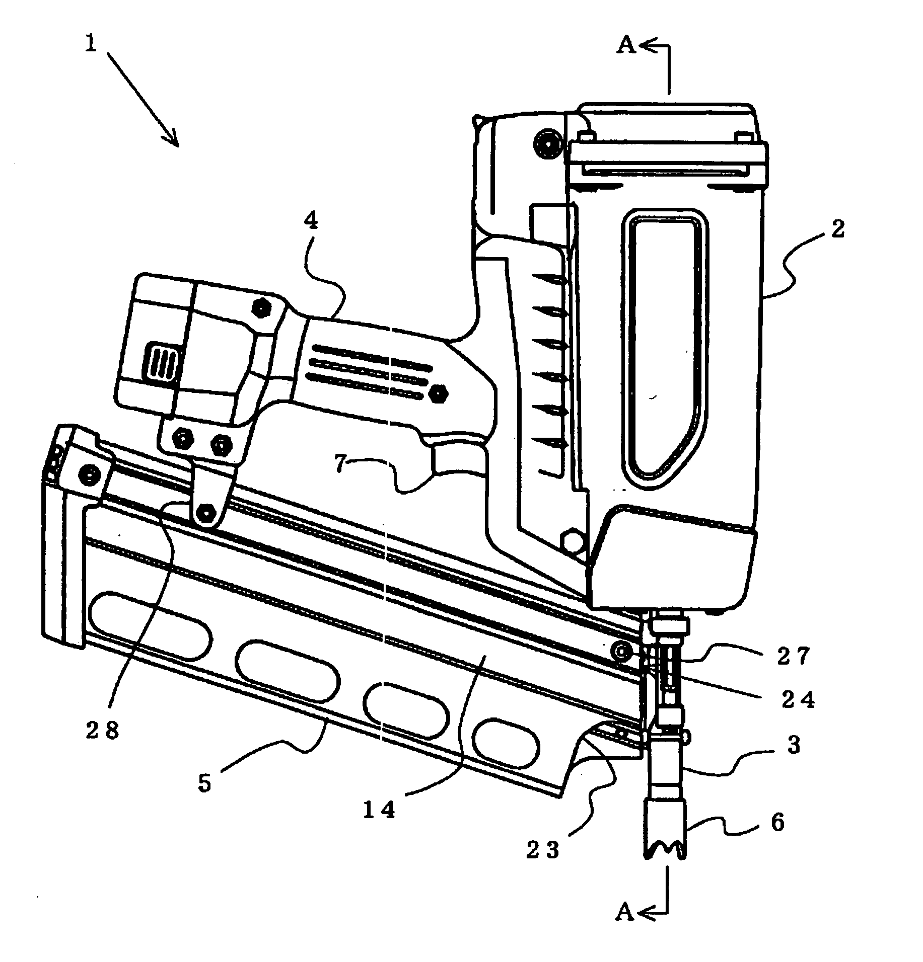
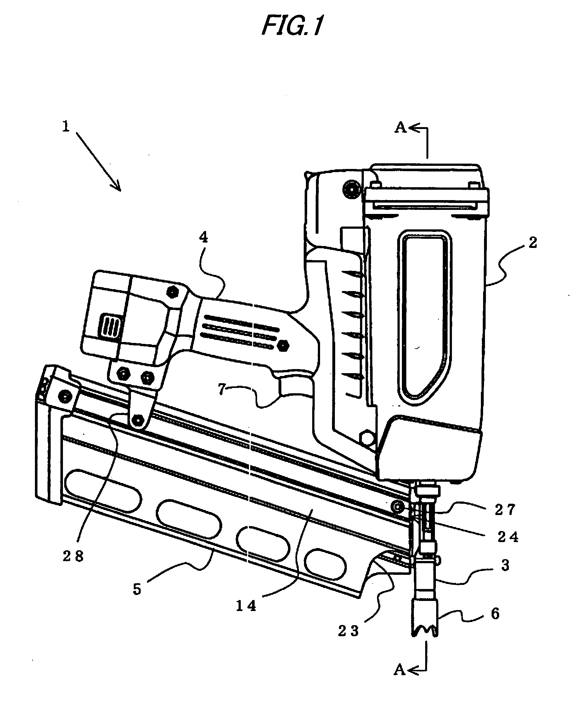
[0034]FIG. 1 shows a power drive nailing machine according to an embodiment of the invention. The power drive nailing machine 1 is constituted by a housing 2 containing an impulse mechanism, a nose portion 3 formed with an injection port for guiding a nail to a struck member and attached to a lower end portion of the housing 2, and a magazine 5 supported between a grip portion 4 integrally formed with a rear side of the housing 2 and a rear side of the nose portion 3 and containing a number of nails. The power drive nailing machine 1 includes a contact member 6 arranged to project in a direction of a front end of the nose portion 3 at ordinary time. The power drive nailing machine 1 is started by bringing the contact member 6 into contact with a struck member to be operated to slide along the nose portion 3 and operating a trigger 7 formed at a base portion of the grip portion 4.

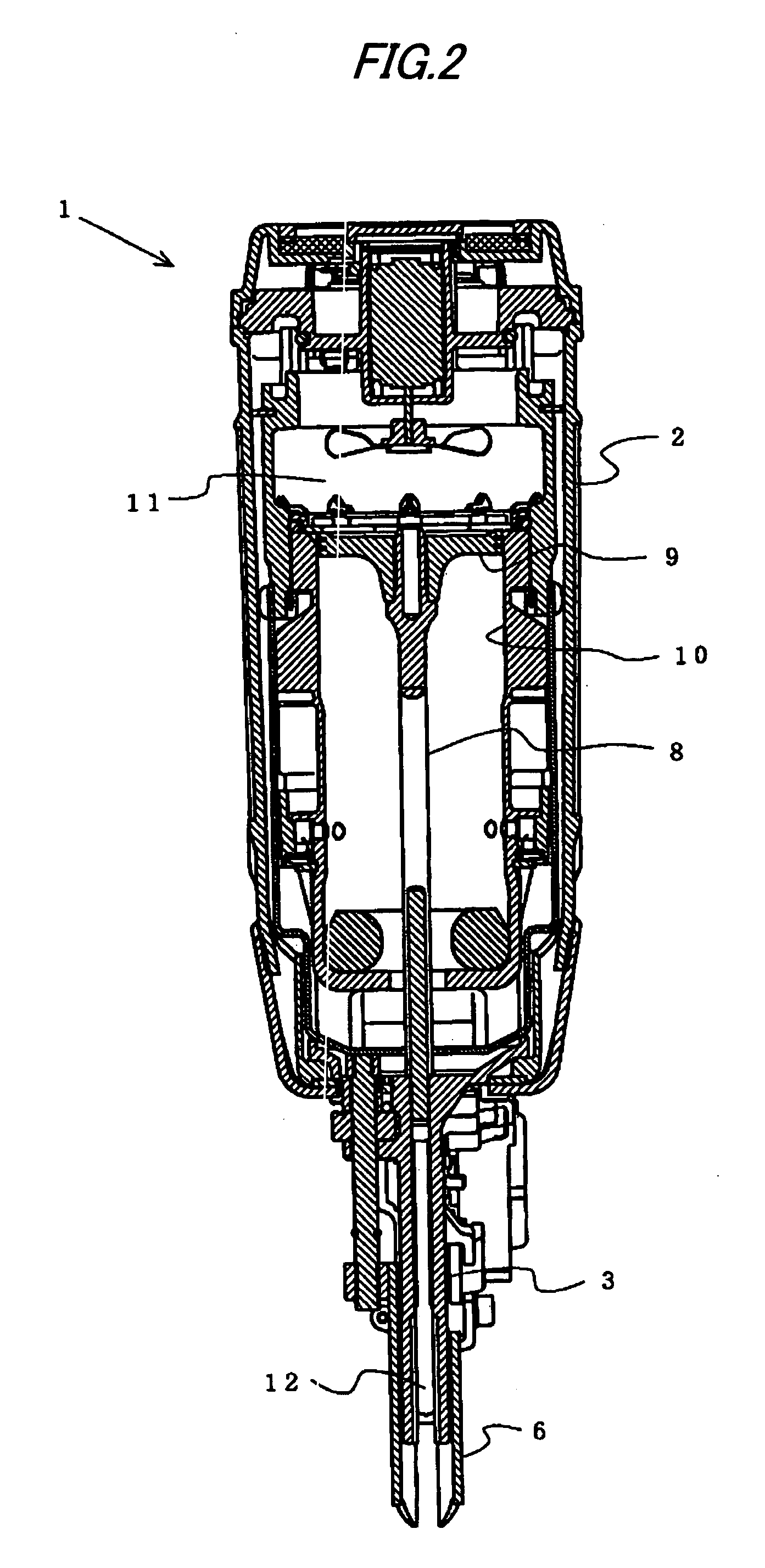
[0035]As shown by FIG. 2, the power drive nailing machine 1 of the embodiment is constituted as a nailing...


PUM


Abstract

A magazine includes guide portions formed at a pair of side walls to be opposed to each other for introducing to guide a portion of a nail shaft portion, an opening portion formed on a base end side of a nose portion relative to the guide portion of one of the side walls, a first attaching portion formed on a front end side of the nose portion relative to the guide portion of the one side wall, a second attaching portion formed on the base end side of the nose portion relative to the guide portion of the other side wall, and a notched portion formed on the front end side of the nose portion relative to the guide portion of the other side wall.

Description

TECHNICAL FIELD[0001]The present invention relates to a power drive nailing machine for striking a fastener of a nail, a pin or the like supplied into an injection port of a nose portion by a driver coupled to a piston to a struck member of wood, concrete, or a steel plate or the like by impulsively driving the piston contained at inside of a cylinder by a pressure of compressed air or a combustion gas or the like.BACKGROUND ART[0002]As a power drive nailing machine, there is a compressed air drive nailing machine, a combustion gas drive nailing machine or the like. The compressed air drive nailing machine drives a piston contained at inside of the cylinder by introducing compressed air into the cylinder and strikes a nail to a struck member of wood or the like by a driver coupled to a piston. The combustion gas drive nailing machine is formed with a combustion chamber at inside of a housing for generating a combustion gas at high pressure by combusting a combustible gas at inside o...

Claims


Application Information

Patent Timeline
Patent Type & Authority Applications(United States)
IPC IPC(8): B25C7/00
CPCB25C1/005B25C1/08B25C7/00
Inventor OSUGA, SATOSHIWATANABE, EIICHI
Owner MAX CO LTD
Why Eureka
Try Eureka