Light source device and projector

a light source device and projector technology, applied in the field of light source devices and projectors, can solve the problems of reducing light utilization efficiency, increasing the size of the device, and unable to achieve the reduction of device size and space saving, so as to reduce the speckle pattern and reduce the light utilization efficiency

Active Publication Date: 2008-10-09
SEIKO EPSON CORP
View PDF6 Cites 60 Cited by
  • Summary
  • Abstract
  • Description
  • Claims
  • Application Information

AI Technical Summary

Benefits of technology

[0029]According to the projector of the second aspect of the invention, the light emitted from the light source device enters the light modulation device. Then, an image formed by the light modulation device is projected by the projection device

Problems solved by technology

However, the related-art technology described above has the following problems.
These speckles are generated by manufacture errors or design errors of the diffraction optical element.
However, the rotation type diffusing plate requires a rotation driving system such as a motor, which increases the size of the device.
Moreover, the rotation type and swing type diffusing plates which diffuse light emitted from the diffraction optical element have positional limitation in positioning these plates and decreases light ut

Method used


Image

  • Light source device and projector
  • Light source device and projector
  • Light source device and projector

Examples


first embodiment

Modified Example of First Embodiment

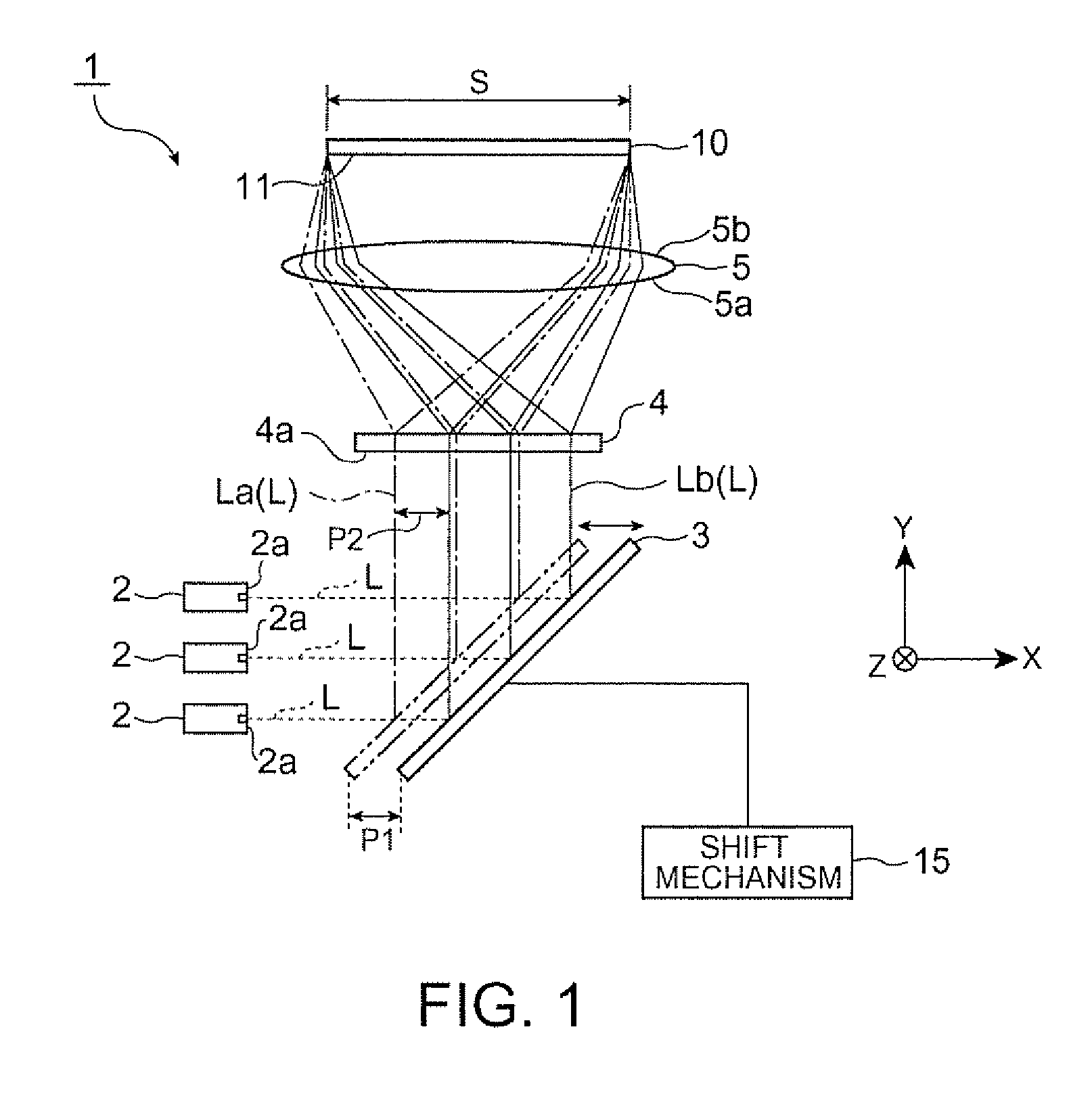
[0074]While the reflection plate 3 is shifted in the X axis direction by parallel displacement by the function of the shift mechanism 15 according to the first embodiment shown in FIG. 1, a light source device 20 which reciprocates the reflection plate in the Y axis direction can be used. A modified example which uses the light source device 20 is now explained with reference to FIG. 3.

[0075]A shift mechanism 21 is a mechanism which shifts the reflection plate 3 for the shift distance P1 in the Y axis direction from a condition indicated by an alternate long and short dash line to a condition indicated by a solid line in FIG. 3. Thus, each center axis of the laser beams L reflected by the reflection plate 3 shifts from the laser beams La (alternate long and short dash line) to the laser beam Lb (solid line) by parallel displacement.

[0076]The light source device 20 having this structure can reduce speckle patterns on the laser beams released from t...

second embodiment

[0079]A second embodiment according to the invention is now described with reference to FIGS. 5A and 5B through 8. In the following embodiments, similar reference numbers are given to parts similar to those of the light source device 1 in the first embodiment, and the same explanation is not repeated.

[0080]A light source device 40 in this embodiment is different from the light source device 1 in the first embodiment in that a shift mechanism 41 shifts the reflection plate 3 such that the reflection plate 3 achieves substantially rotational movement. Other structures are similar to those in the first embodiment.

[0081]As illustrated in FIGS. 5B and 6B, the shift mechanism (shift unit) 41 has a support member 42 and a connection member 43. The support member 42 corresponds to a rotation axis P of the reflection plate 3, and rotates the connection member 43 around the rotation axis P. An end 43a of the connection member 43 is supported by the support member 42, and the other end 43b is ...

modified example 1 of second embodiment

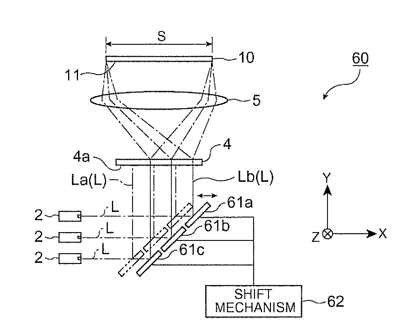
[0088]While the reflection plate 3 is continuously shifted by the substantial rotation of the reflection plate 3 in the second embodiment shown in FIGS. 5A and 5B and FIGS. 6A and 6B, a plurality of reflection plates (optical path converting units) 51a and 51b may be provided and continuously shifted. This modified example is now described with reference to FIG. 7.

[0089]As illustrated in FIG. 7, the reflection plate 51a is disposed such that the laser beams L emitted from the plural laser beam sources 2 enter the reflection plate 51a at 45 degrees. Thus, the laser beams L reflected by the reflection plate 51a travel in the X axis direction. The reflection plate 51b is disposed such that the laser beams L reflected by the reflection plate 51a enter the reflection plate 51b at 45 degrees. Thus, the reflection plate 51b reflects the entering laser beams L toward the hologram element 4 in the Y axis direction.

[0090]A shift mechanism 52 is attached to the reflection plates 51a and 51b. T...


PUM


Abstract

A light source device which produces illumination light for illuminating a target illumination area on a predetermined light receiving surface includes: a light source which emits light; a superimposing illumination element which superimposes the light emitted from the light source and applies the light to the target illumination area; an optical path converting unit disposed on an optical path between the light source and the superimposing illumination element to convert the optical path of the light emitted from the light source and supply the light having the converted optical path to the superimposing illumination element; and a shift unit which shifts the optical path converting unit.

Description

BACKGROUND[0001]1. Technical Field[0002]The present invention relates to a light source device and a projector.[0003]2. Related Art[0004]Currently, a technology of incorporating a laser beam source in a projection type image display apparatus (projector) has been proposed, which display apparatus projects color light containing image information produced by a spatial light modulating device such as a liquid crystal device on a screen by using a projection system (for example, see JP-A-2007-33576).[0005]A lighting device disclosed in JP-A-2007-33576 includes a light source device for emitting light and a diffraction optical element for equalizing illuminance distribution of entering light. The lighting device applies rectangular conversion to light emitted from the light source device by using the diffraction optical element and illuminates a predetermined illumination area. The projection type image display apparatus having this lighting device includes a light valve disposed oppose...

Claims


Application Information

Patent Timeline
IPC IPC(8): G02B26/08G02B27/48
CPCG02B27/48G02B2207/117G03H1/08G03H2001/085
Inventor YAMAUCHI, TAISUKETAKEDA, TAKASHI
Owner SEIKO EPSON CORP
Why Eureka
Try Eureka