Distributed Patient Monitoring System

a patient monitoring and distribution system technology, applied in the field of distribution patient monitoring system, can solve the problems of inflexible performance and architecture, failure to accommodate high bandwidth communication of patient related data, and burdensome and laborious task of monitoring patients, especially patients in critical car

Inactive Publication Date: 2008-10-09
CERNER INNOVATION
View PDF43 Cites 147 Cited by
  • Summary
  • Abstract
  • Description
  • Claims
  • Application Information

AI Technical Summary

Problems solved by technology

Monitoring of patients, particularly patients in critical care is a burdensome and labor intensive task.
However it is fixed in location, inflexible in performance and architecture and fails to accommodate high bandwidth communication of patient related data.

Method used


Image

  • Distributed Patient Monitoring System
  • Distributed Patient Monitoring System
  • Distributed Patient Monitoring System

Examples


Embodiment Construction

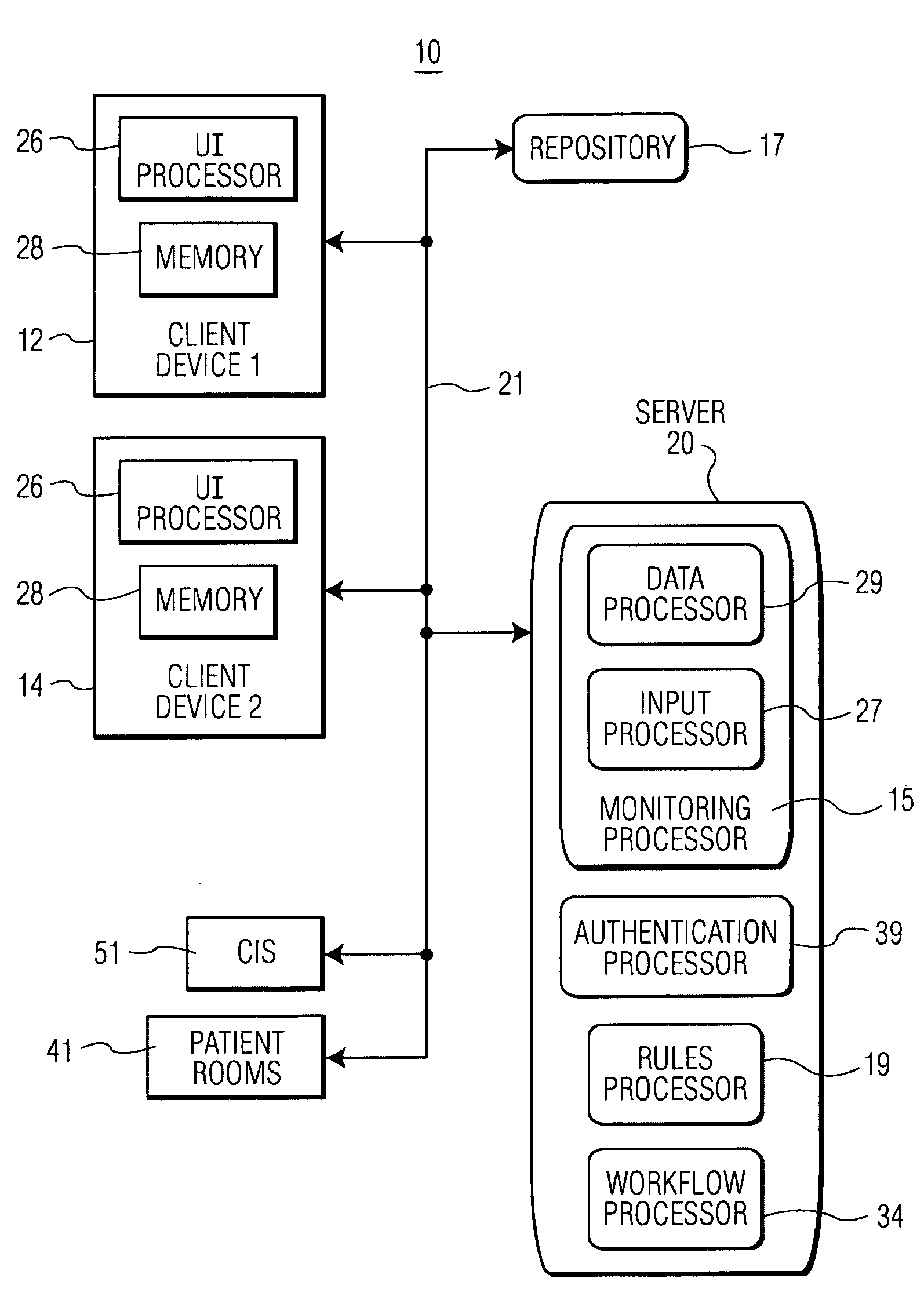
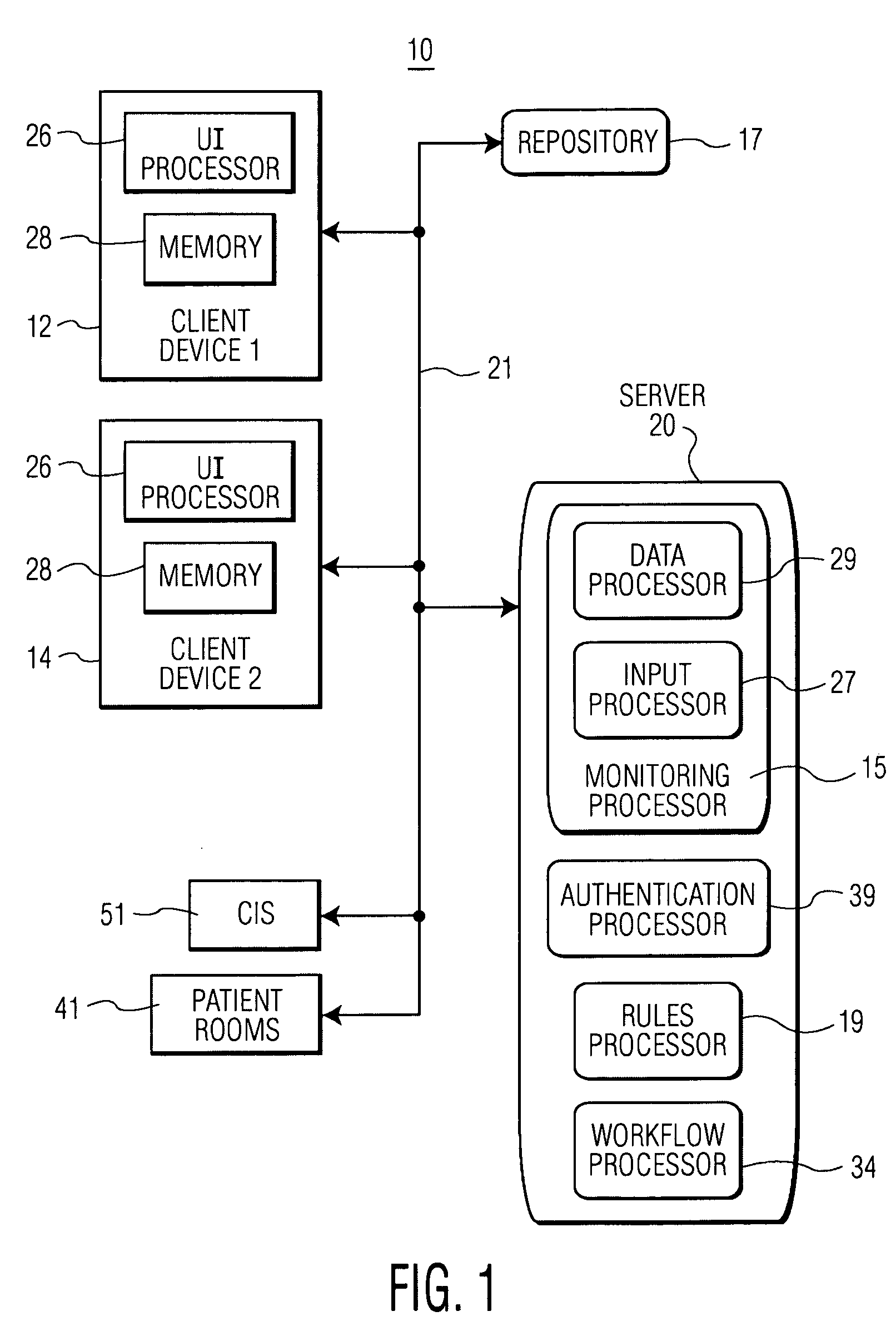
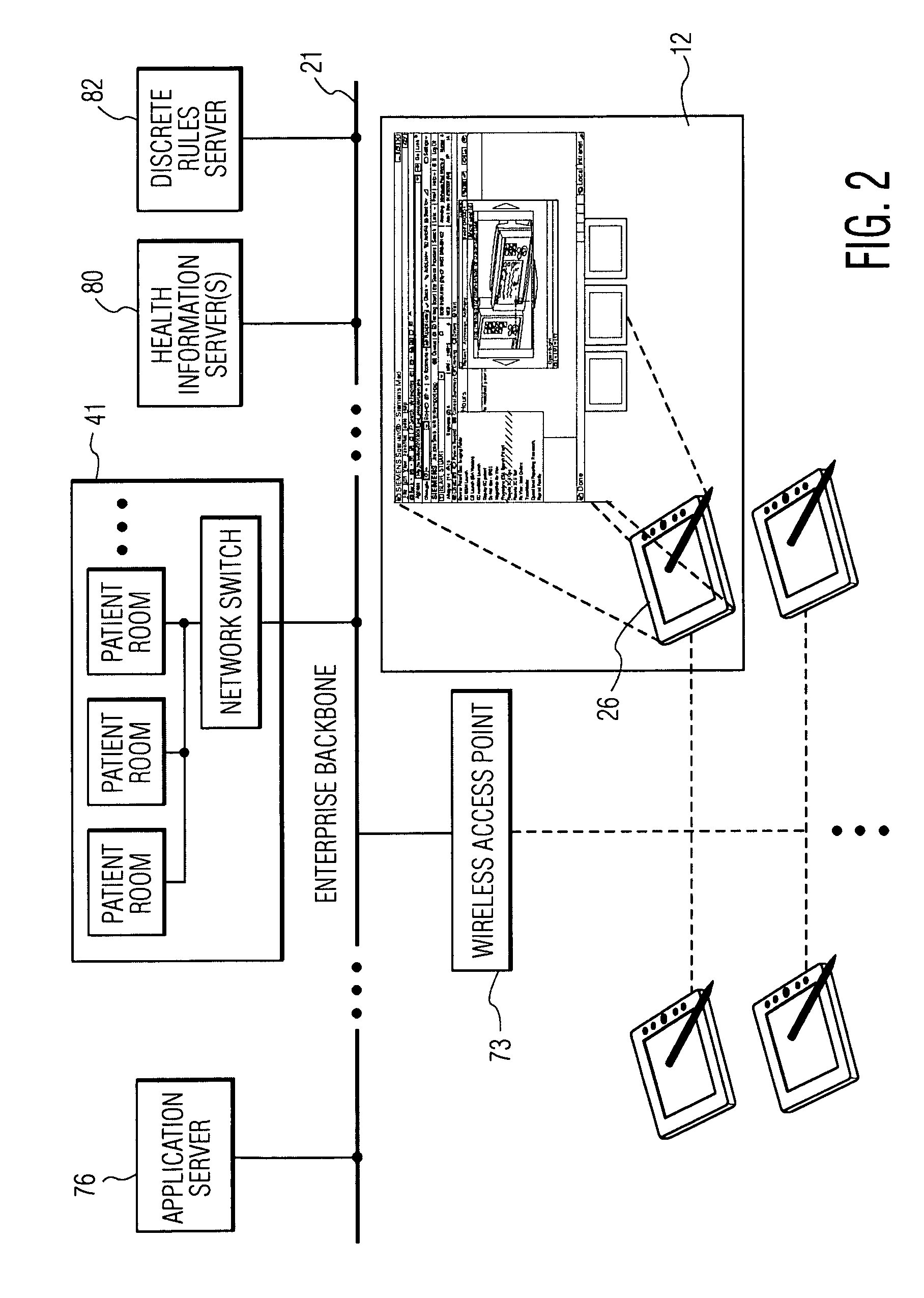
[0014]A distributed patient monitoring system enables a user to visually monitor patients and patient parameters using live motion video and audio data presented on multiple portable processing devices in different remote locations comprising distributed personal command centers. A mobile or stationary clinician in a healthcare enterprise monitors live motion video and audio data of a patient within a hospital room presented using a Web browser on a wireless tablet personal computer, palm pilot or other portable device. Execution of an individual command center application is initiated from within a patient specific display image view presenting specific patient electronic medical record data, in response to user selection of a specific patient related item or an item in a patient census list, for example. Patient identifier information is employed in acquiring video and audio data of a particular patient using association of the patient identifier with patient medical information a...


PUM


Abstract

A distributed patient monitoring system for visually monitoring patients and patient parameters using portable processing devices in different remote locations includes a monitoring processor. The monitoring processor is responsive to user initiated commands from multiple different portable processing devices in different remote locations and includes an input processor and a data processor. The input processor acquires vital sign parameters and associated video data representative of multiple sequences of video images of corresponding multiple different patients. The data processor processes the vital sign parameters and associated video data to provide processed first video data representing an image sequence including a composite image including a first area showing live video of a selected first patient and a second area presenting vital sign parameters of the selected first patient. The data processor also processes the vital sign parameters and associated video data to provide processed second video data representing an image sequence including a composite image including a first area showing live video of a selected second patient and a second area presenting vital sign parameters of the selected second patient. A communication network has bandwidth sufficient to communicate the processed first video data and second video data to first and second portable processing devices respectively of the multiple different portable processing devices in different remote locations in response to commands received from the first and second portable processing devices respectively.

Description

[0001]This is a non-provisional application of provisional application Ser. No. 60 / 910,674 filed Apr. 9, 2007 and of provisional application Ser. No. 60 / 911,302 filed Apr. 12, 2007, by J. R. Zaleski.FIELD OF THE INVENTION[0002]This invention concerns a distributed patient monitoring system for visually monitoring patients and patient parameters using a plurality of portable processing devices in different remote locations.BACKGROUND OF THE INVENTION[0003]Monitoring of patients, particularly patients in critical care is a burdensome and labor intensive task. This problem has been addressed by use of a centralized monitoring facility enabling a physician at the workstation of the centralized monitoring facility to monitor patient vital signs and video and audio. One known remote centralized patient monitoring system, described in U.S. Pat. No. 6,804,656, provides fixed location, static centralized monitoring of ICUs by a physician. The centralized monitoring employs a single command c...

Claims


Application Information

Patent Timeline
Patent Type & Authority Applications(United States)
IPC IPC(8): A61B5/00G16H30/20G16H40/67
CPCA61B5/0006G06Q40/08G06Q50/22G06Q50/24A61B5/7232A61B5/0013G16H30/20G16H40/67
Inventor ZALESKI, JOHN R.
Owner CERNER INNOVATION
Why Eureka
Try Eureka