
Automated wheelchair

a wheelchair and automatic technology, applied in the field of automatic wheelchairs, can solve the problems of inability to perform tasks, inability to go over a curb, up or down a set of stairs, and inability to travel over rough terrain

Active Publication Date: 2008-10-16
FRIE THOMAS T
View PDF9 Cites 28 Cited by
  • Summary
  • Abstract
  • Description
  • Claims
  • Application Information

AI Technical Summary

Benefits of technology

[0004]The present invention provides an automated wheelchair for moving over a contact surface. The automated wheelchair includes an operator chair for seating the wheelchair operator, a control computer, an operator input device for transmitting operator inputs to the control computer, and two wheelchair wheels for propelling the wheelchair. Each wheelchair wheel includes extendable and retractable spokes. The extension and retraction of each spoke is controlled by a motor. At the ends of each spoke are contact sensor devices. The control computer is programmed to receive inputs transmitted from the contact sensor devices to generate a terrain profile. The control computer generates and sends control signals to each spoke...

Problems solved by technology

However, despite recent improvements in technology and intense recent interest in wheelchairs, the modern wheelchair varies just slightly from traditional designs.
Most importantly modern wheelchairs are incapable of performing tasks that non-wheelchair users take for granted continuously throughout the day.
For example, prior art wheelchairs are incapable of going over a curb, up or down a set of stairs or traveling over rough terrain.

Method used


Image

  • Automated wheelchair
  • Automated wheelchair
  • Automated wheelchair

Examples


Embodiment Construction

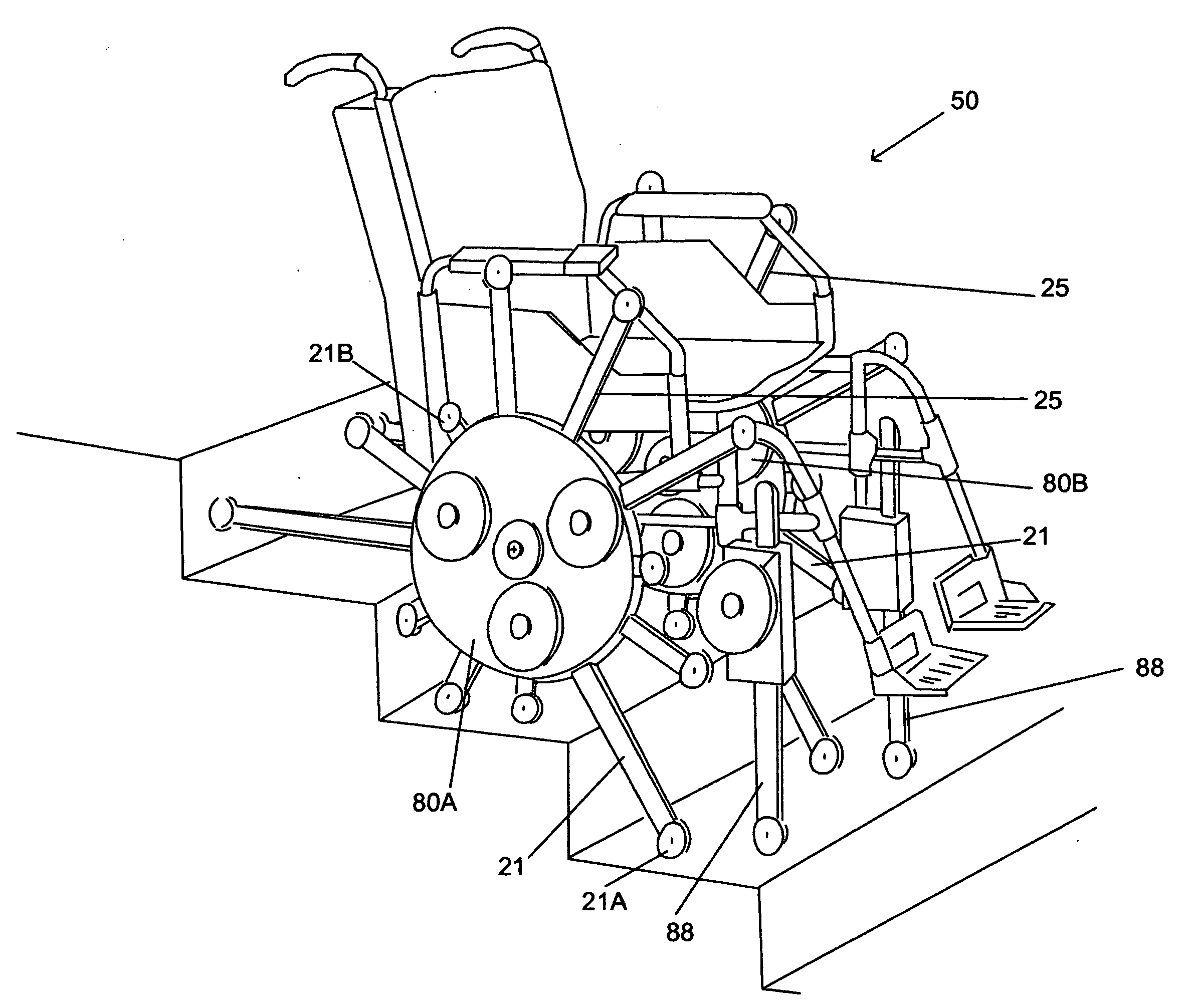
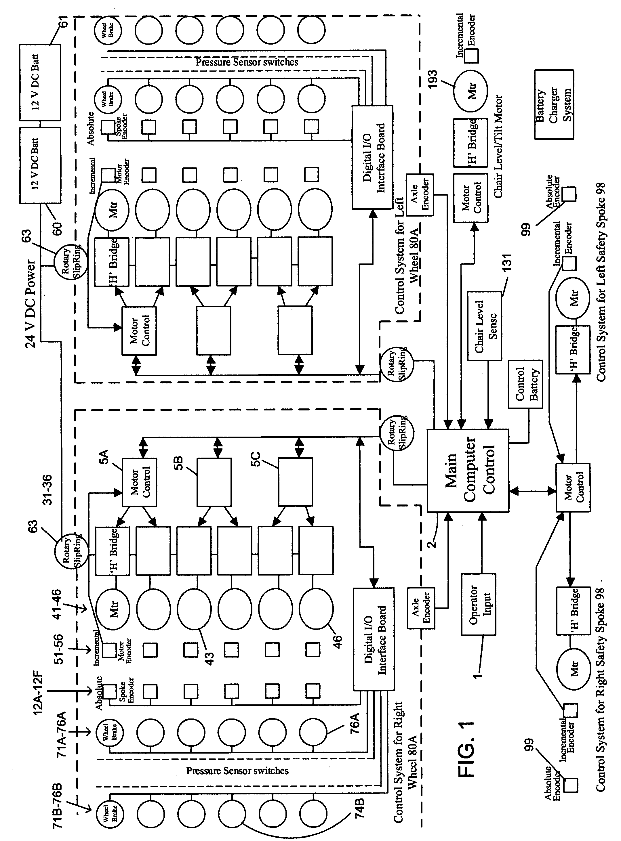
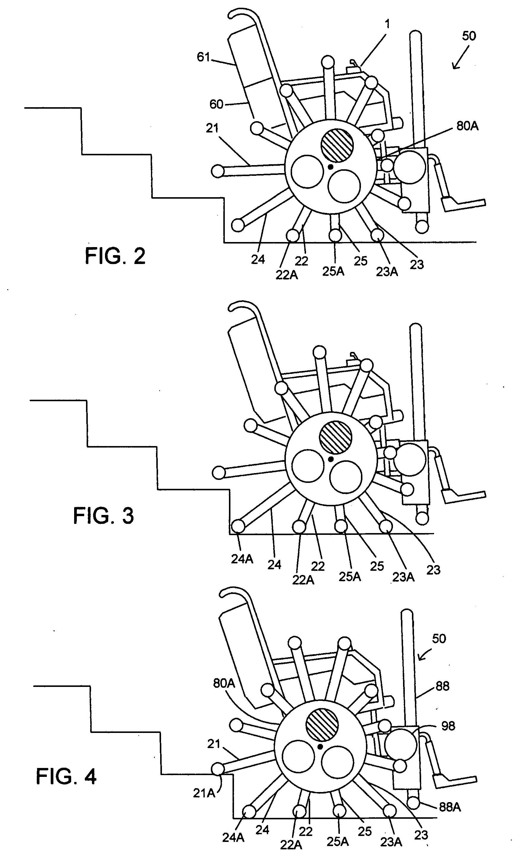
[0018]FIG. 23 shows a perspective view and FIG. 1 shows a block diagram of a preferred embodiment of the present invention.

[0019]Main computer controller 2 receives operator inputs via operator input device 1. Corresponding control signals are sent to wheels 80A and 80B. Wheels 80A and 80B each include 6 spokes 21-26 that are controlled via motors 41-46 (see also FIG. 1). At each end of each spoke are pneumatic wheels. For example, pneumatic wheels 21A and 21B are attached to opposite ends of spoke 21. Each pneumatic wheel includes a pressure sensor. When a pneumatic wheel makes contact with a surface, the pressure within the wheel increases and a signal is sent back to main computer controller 2. Main computer controller 2 records this data. The data includes the angle of the spoke and the extension of the spoke when surface contact was made. Main computer controller 2 is programmed to compile this data received from pressure sensors and to utilize this data to calculate a terrain ...


PUM


Abstract

An automated wheelchair for moving over a contact surface. The automated wheelchair includes an operator chair for seating the wheelchair operator, a control computer, an operator input device for transmitting operator inputs to the control computer, and two wheelchair wheels for propelling the wheelchair. Each wheelchair wheel includes extendable and retractable spokes. The extension and retraction of each spoke is controlled by a motor. At the ends of each spoke are contact sensor devices. The control computer is programmed to receive inputs transmitted from the contact sensor devices to generate a terrain profile. The control computer generates and sends control signals to each spoke motor in response to the operator inputs and in response to the terrain profile generated by the contact sensor devices. In a preferred embodiment the contact sensor devices are pressure sensor devices. Also in a preferred embodiment, rotatable pneumatic wheels are attached to both ends of each spoke. Preferably, a brake is applied to at least one pneumatic wheel per wheelchair wheel while the wheelchair is moving over the contact surface. Preferably, the automated wheelchair is capable of moving over a variety of contact surface types, including: a set of stairs with uniform rise to run ratio, a set of stairs with non-uniform rise to run ratio, a set of straight stairs, a set of curved stairs, over a curb or over rough terrain.

Description

[0001]The present invention relates to wheelchairs, and in particular, to automated wheelchairs.BACKGROUND OF THE INVENTION[0002]Wheelchair usage has received recent attention in the media. It has been estimated that currently approximately 2 million Americans use wheelchairs. This number is expected to grow dramatically as the baby boomer generation grows elderly, as the population increases and as the age of life expectancy increases. Also, there has been recent media coverage on injured veterans from the war in Iraq and on mobility assistance devices such as wheelchairs and prosthetic limbs. However, despite recent improvements in technology and intense recent interest in wheelchairs, the modern wheelchair varies just slightly from traditional designs. Most importantly modern wheelchairs are incapable of performing tasks that non-wheelchair users take for granted continuously throughout the day. For example, prior art wheelchairs are incapable of going over a curb, up or down a s...

Claims


Application Information

Patent Timeline
IPC IPC(8): A61G5/06
CPCA61G5/04A61G5/061A61G5/065A61G5/068A61G2203/14
Inventor FRANKIE, THOMAS T.
Owner FRIE THOMAS T
Learn More