Folded-monopole whip antenna, associated communication device and method

a technology of antenna and monopoly antenna, applied in the field of communications, can solve the problems of insufficient stress on the antenna environment, inductive loading, and imposing demanding requirements on the antenna matching system, and achieve the effect of increasing gain and rang

Active Publication Date: 2008-10-16
HARRIS CORP
View PDF6 Cites 24 Cited by
  • Summary
  • Abstract
  • Description
  • Claims
  • Application Information

AI Technical Summary

Benefits of technology

[0015]In view of the foregoing background, it is therefore an object of the present invention to provide a wireless communication device with a smaller whip antenna having increased gain and range.

Problems solved by technology

But, because many whip antennas are electrically small or operated with a poor electrical ground system, they can be inefficient.
The rigors of the military whip antenna environment cannot be understated.
The operator may stand, walk, or lie on the ground, which imposes demanding requirements on the antenna matching system.
A limitation arises however when these whip or monopole antennas become electrically short: inductive loading is required and the associated loading “coil” can have resistive losses.
In fact, if made short enough, all inductor loaded monopole antennas will become inefficient and have low gain.
Larger and larger loading inductance is required with decreasing whip lengths, causing decreasing efficiency.
Inductive driving impedances occur in small loop antennas, but loops can be physically unwieldy for portable radio communications.

Method used


Image

  • Folded-monopole whip antenna, associated communication device and method
  • Folded-monopole whip antenna, associated communication device and method
  • Folded-monopole whip antenna, associated communication device and method

Examples


Embodiment Construction

[0030]The present invention will now be described more fully hereinafter with reference to the accompanying drawings, in which preferred embodiments of the invention are shown. This invention may, however, be embodied in many different forms and should not be construed as limited to the embodiments set forth herein. Rather, these embodiments are provided so that this disclosure will be thorough and complete, and will fully convey the scope of the invention to those skilled in the art. Like numbers refer to like elements throughout. The dimensions of various layers may be exaggerated for illustration purposes.

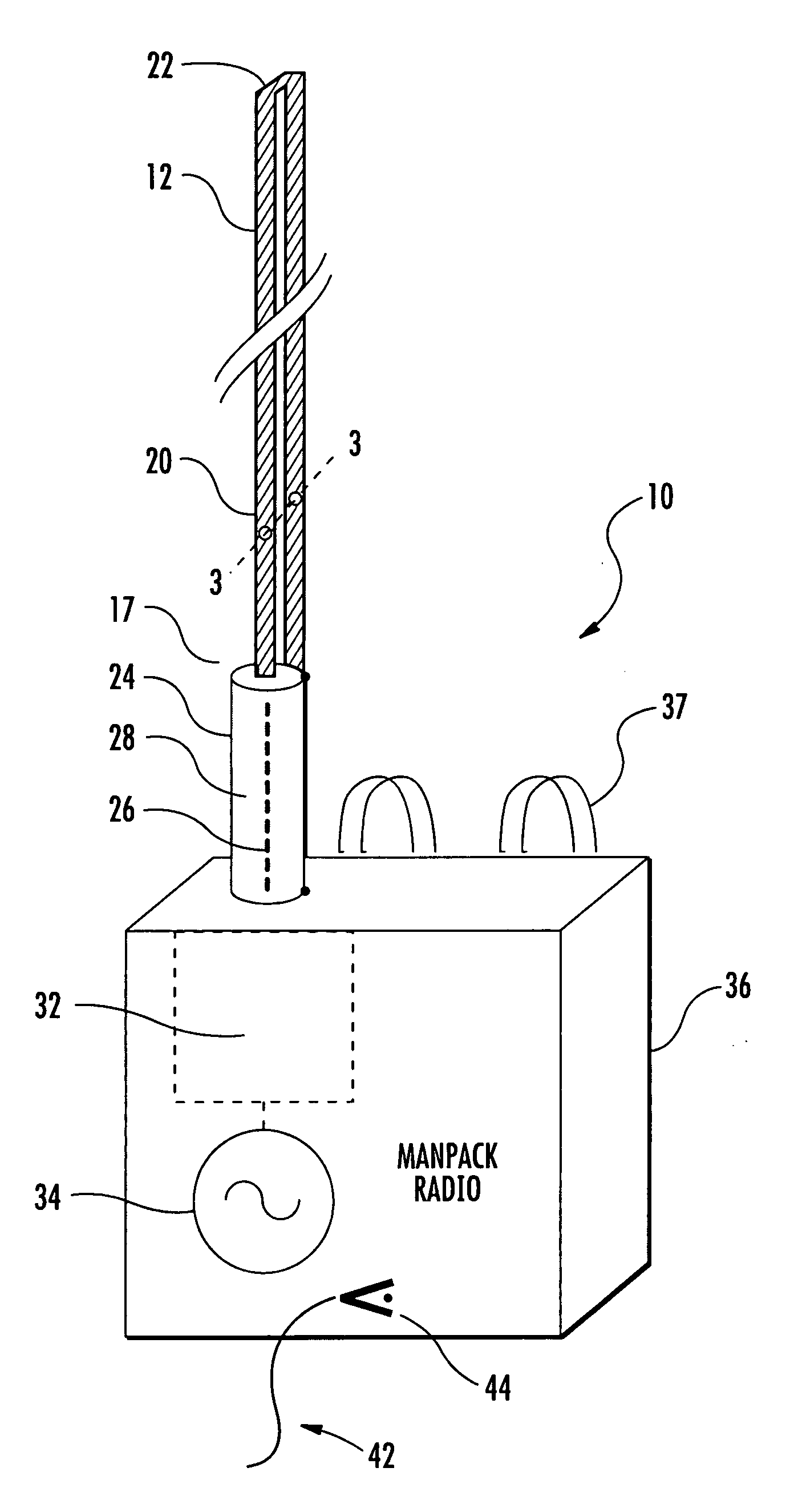
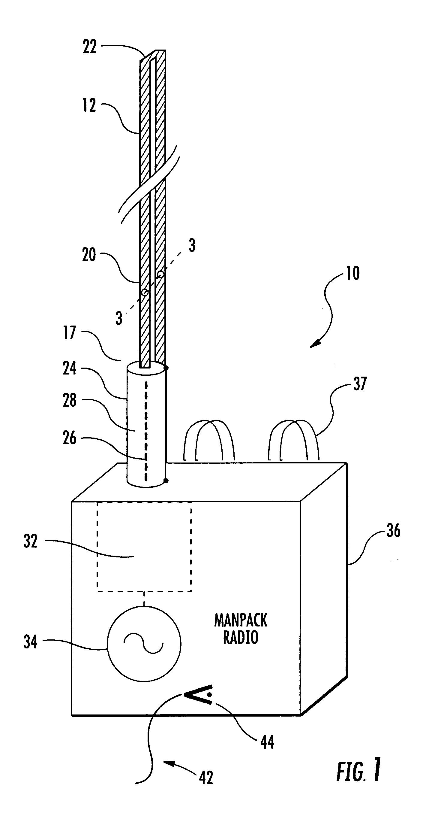
[0031]Referring initially to FIGS. 1, 2 and 4, a portable wireless communication device 10 including a flexible whip antenna 12 of the folded monopole type, will now be described. The portable wireless communication device 10 includes a portable housing 36, wireless communication circuitry 34 carried by the housing, and a flexible antenna 12 extending outwardly from the housing ...


PUM


Abstract

The folded-monopole whip antenna is for a portable wireless communication device having a portable housing and wireless communication circuitry carried thereby. The antenna includes a flexible antenna element extending outwardly from the housing and having a proximal end for coupling to the wireless communication circuitry and having a distal end spaced from the proximal end. The flexible antenna element may have first and second flexible elongate legs or whips extending parallel to one another. The first flexible elongate leg may have a proximal end defining a first antenna feedpoint to be coupled to the wireless communication circuitry, and the second flexible elongate leg may have a proximal end defining a second antenna feedpoint to be coupled to the portable housing. The first and second flexible elongate legs may have distal ends electrically coupled to one another. A dielectric layer may be fastened between the first and second flexible elongate legs. The folded-monopole whip antenna may provide a tactical military antenna for manpack radio requirements, with greater gain, smaller size and reduced visability at HF and VHF frequencies. It may use capacitor only matching across broad tunable bandwidths, and an elevated feedpoint for increased efficiency and RF safety.

Description

FIELD OF THE INVENTION[0001]The present invention relates to the field of communications, and, more particularly, to antennas for mobile wireless communication and related methods.BACKGROUND OF THE INVENTION[0002]A monopole antenna is a type of radio antenna formed by replacing one half of a dipole antenna with a ground plane at right-angles to the remaining half. If the ground plane is large enough, the monopole becomes similar to a dipole, as if its reflection in the ground plane forms the missing half of the dipole. Examples of monopole antennas include the whip antenna and the radio mast when isolated from the ground and bottom-fed.[0003]The whip antenna is often a flexible springy wire mounted, usually vertically, with one end adjacent to a ground plane. A whip antenna can be a half element antenna that can be used with an unbalanced feed line such as coaxial cable, or attached directly to a wireless transmitter, receiver, or transceiver, in which case the radio case becomes th...

Claims


Application Information

Patent Timeline
Patent Type & Authority Applications(United States)
IPC IPC(8): H01Q1/24
CPCH01Q1/085H01Q1/242H01Q9/42
Inventor PARSCHE, FRANCIS EUGENE
Owner HARRIS CORP
Why Eureka
Try Eureka