Lens barrel

a barrel and lens technology, applied in the field of lenses barrels, can solve the problems of difficult mounting and assembly the shape becomes larger, and the mounting method of the lens frame-protecting member and the bumper member is difficult, so as to achieve the effect of enhancing impact resistance, preventing breakage and so on of the lens barrel, and simplifying structur

Inactive Publication Date: 2008-10-16
RICOH KK
View PDF7 Cites 0 Cited by
  • Summary
  • Abstract
  • Description
  • Claims
  • Application Information

AI Technical Summary

Benefits of technology

[0011]The present invention has been made in view of the above problems in the prior art and an object thereof is to provide a lens barrel in which impact-resistance is enhanced while a structure is simplified, breakage and so on of the lens barrel are prevented, and an assembly is easy.

Problems solved by technology

However, because the conventional lens barrel as described above is double-structure of the lens frames and the lens frame-protecting member, there is a problem that the shape becomes larger.
Moreover, if the exterior force is added, because the bumper member is moved, there is a problem that mounting and assembly of the lens frame-protecting member and the bumper member are complex and difficult.
Furthermore, when the exterior force is added, because the bumper member is moved, a mounting method of the lens frame-protecting member and the bumper member is very difficult.

Method used


Image

  • Lens barrel
  • Lens barrel
  • Lens barrel

Examples


first embodiment

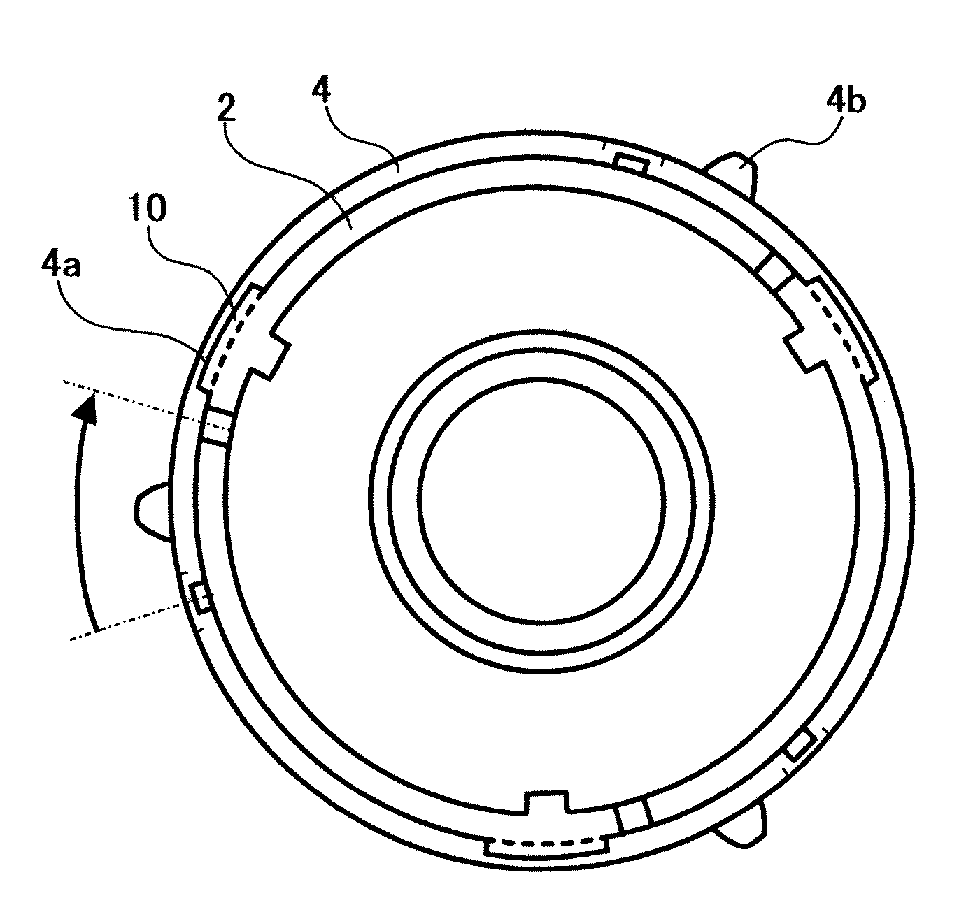
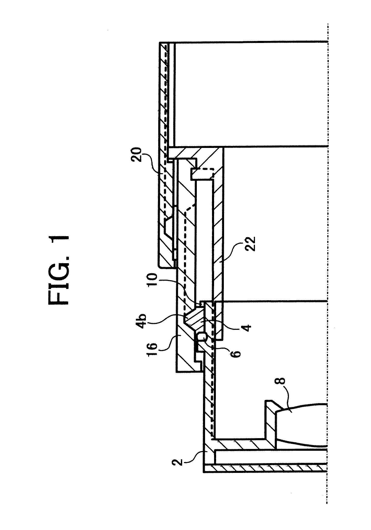
[0055]the present invention is illustrated in FIGS. 1 to 3. As shown in FIG. 1, a lens barrel according to the present invention comprises a moving frame 2 to hold a lens 8, a direct-advance ring 4 disposed on an outer periphery of the moving frame 2 and movable relative to the moving frame in an optical direction, and a resilient member 6 disposed between the moving frame 2 and the direct-advance ring 4.

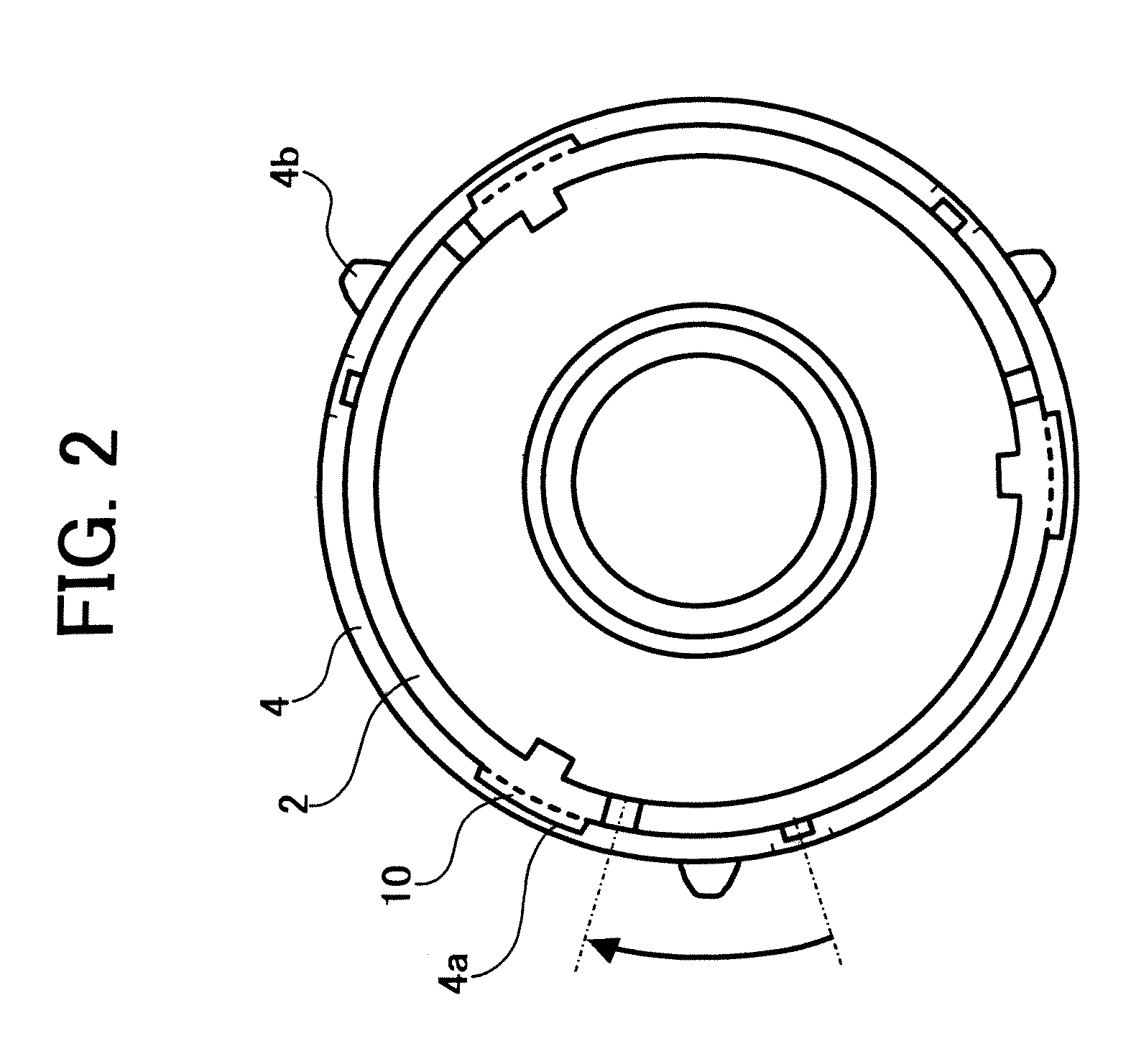
[0056]The resilient member 6 comprises, preferably a spring or rubber. In the illustrated embodiment, the resilient member 6 comprises an O-ring attached to the moving frame 2. Meanwhile, FIGS. 2 and 3 show the moving frame 2 and the direct-advance ring 4 as viewed from the opposite side to a subject.

[0057]The moving frame 2 is provided with one or more control parts 10 to control the movement of the direct-advance ring 4 in the optical direction. The direct-advance ring 4 is provided with one or more cutout portions, in which the control part 10 can be inserted. In a position shown...

second embodiment

[0065]The resilient member 6, also, comprises, preferably a spring or rubber. In the second embodiment, the resilient member 6, also, comprises an O-ring attached to the moving frame 2. Meanwhile, FIGS. 6 and 7 show the moving frame 2 and the direct-advance ring 4 as viewed from the opposite side to the subject.

[0066]In the second embodiment, as shown in FIG. 5, there is provided a direct-advance guiding member 22, which moves with, for example, the cam frame 16 in the optical direction and is regulated by a fixing frame 20 to perform only direct movement. The moving frame 2 is controlled by means of the direct-advance guiding member 22 to be movable only direct advance.

[0067]Moreover, as shown in FIGS. 6 and 7, the moving frame 2 is provided with a rotational control part 30 to control the movement of the direct-advance ring 4 in a rotational direction, a pin 32 is provided as a control part to regulate an amount of movement of the direct-advance ring 4 in the optical direction at ...

third embodiment

[0070]FIG. 11 to 13 illustrates the present invention. As shown in FIG. 11, a lens barrel in the embodiment comprises a moving frame 2 to hold a lens 8, a direct-advance ring 4 disposed on an outer periphery of the moving frame 2 and movable relative to the moving frame in an optical direction, and a resilient member 6 disposed between the moving frame 2 and the direct-advance ring 4, similarly as the above-mentioned embodiments.

[0071]The resilient member 6, also, comprises, preferably a spring or rubber. In the second embodiment, the resilient member 6, also, comprises an O-ring attached to the moving frame 2. Meanwhile, FIGS. 12 and 13 show the moving frame 2 and the direct-advance ring 4 as viewed from the opposite side to the subject.

[0072]Provided on the direct-advance ring 4 is a plurality of shafts 40 which are engaged with the cam frame 16 and so on, and control the movements of the direct-advance ring 4 in the rotational and optical directions relative to the moving frame 2...


PUM


Abstract

A lens barrel, including, a moving frame (2) to hold a lens (8), a direct-advance ring (4) provided on an outer periphery of the moving frame and movable relative to the moving frame in an optical direction, a resilient member (6) provided between the moving frame and the direct-advance ring, and a control part (10) provided on the moving frame to control an amount of movement of the direct-advance ring in the optical direction.

Description

CROSS REFERENCE TO THE RELATED APPLICATION[0001]This application is a divisional of U.S. application Ser. No. 10 / 913,549, filed Aug. 9, 2004 which claims the priority benefit of Japanese Patent Application Nos. 2003-292055 filed on Aug. 12, 2003, and 2003-399418 filed on Nov. 28, 2003, the entire descriptions of which are incorporated herein by reference.BACKGROUND OF THE INVENTION[0002]1. Field of the Invention[0003]The present invention relates to a lens barrel settable in an optical device such as a camera or the like, particularly to a lens barrel[0004]2. Description of Related Art[0005]Generally, there is provided a shock-absorbing member in a lens barrel for holding a lens in order to protect an optical part such as the lens or the like from an impact or vibrations in a silver film camera, a digital camera or the other optical devices.[0006]Conventionally, there has been known a lens barrel to prevent breakage of a lens, as disclosed in Japanese Patent Laid-Open 2001-116974, f...

Claims


Application Information

Patent Timeline
Patent Type & Authority Applications(United States)
IPC IPC(8): G02B7/02G02B7/04G03B17/00G02B7/08
CPCG02B7/08G02B7/02
Inventor NUNO, KATSUHIKOTSURUKAWA, IKUYAITO, KAORUSHINOHARA, JUNICHIETOH, AKIHIRO
Owner RICOH KK
Why Eureka
Try Eureka