

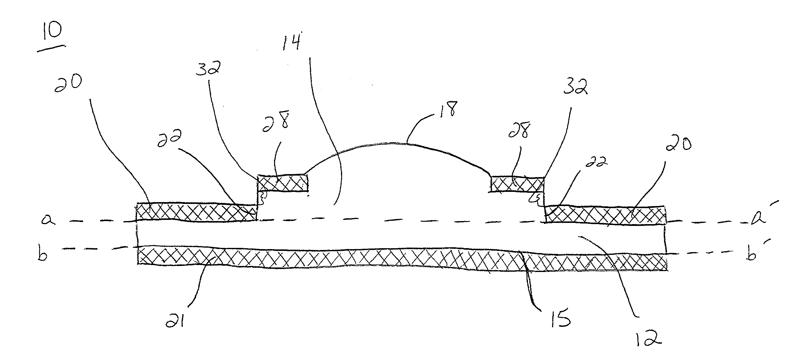
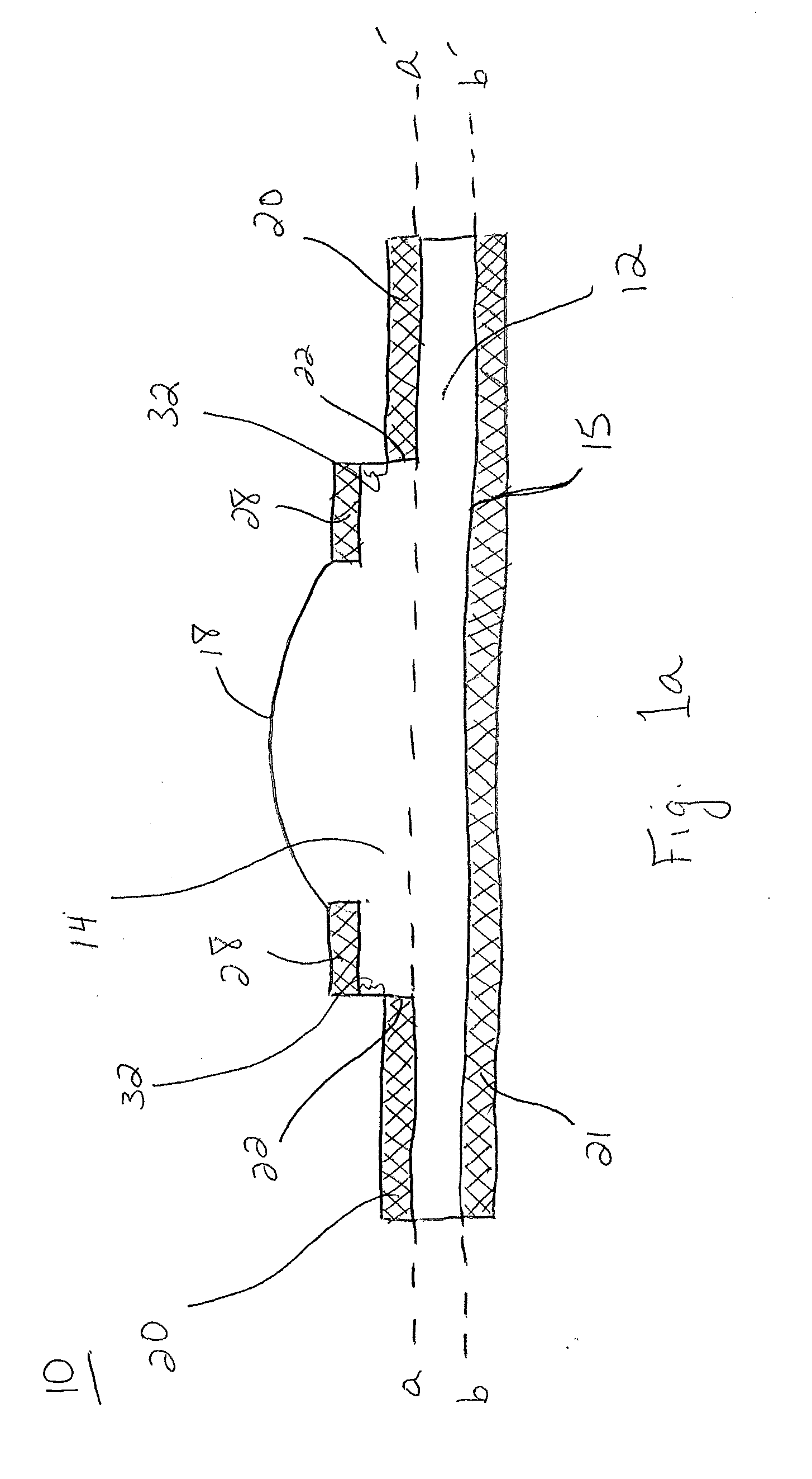
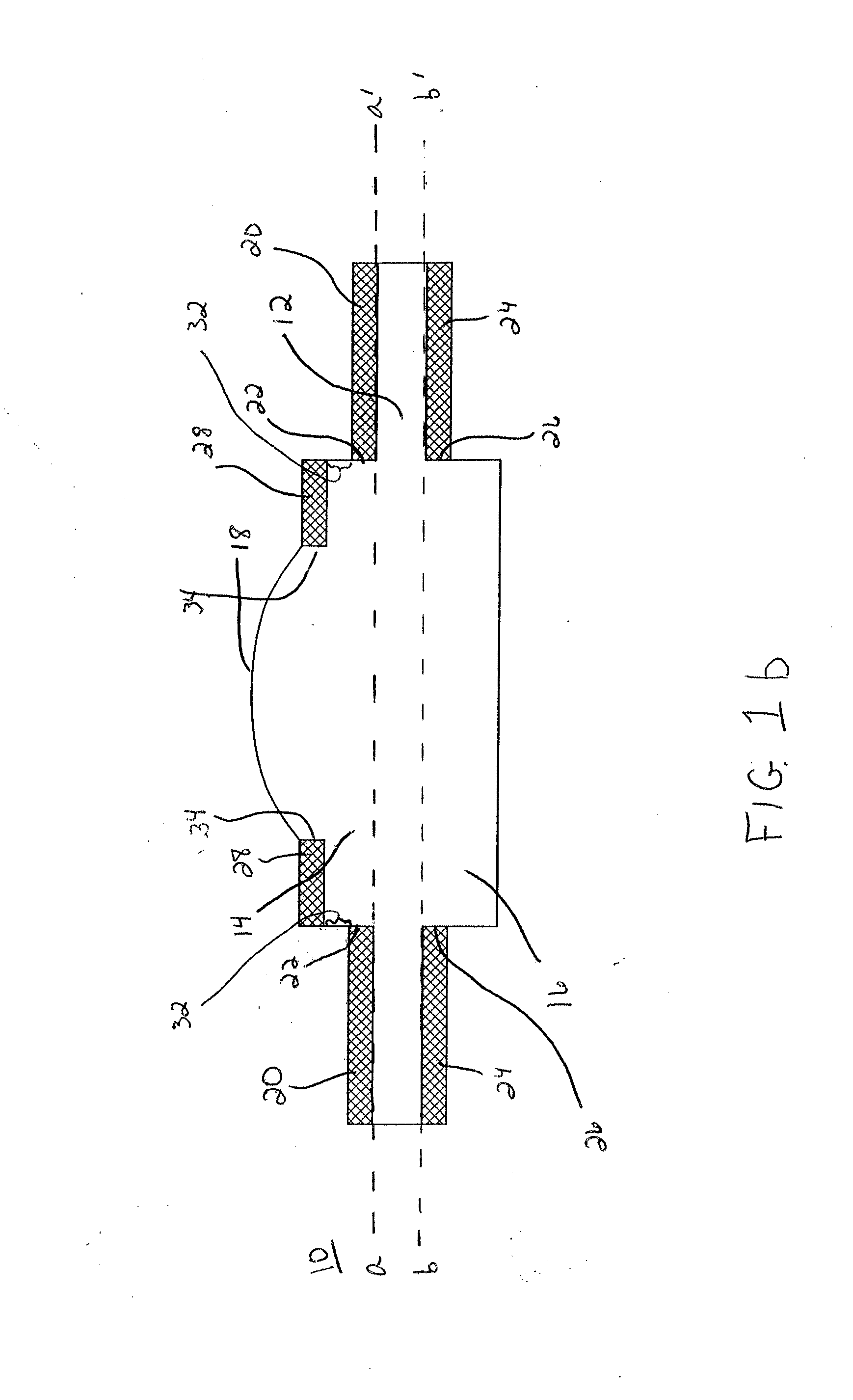
Artificial Cornea and Method of Making Same
a technology of artificial cornea and cornea, which is applied in the field of artificial cornea, can solve the problems of hampered keratoprosthesis efficacy, hampered keratoprosthesis efficacy, and inability to biointegrate or extrude the device from the eye, so as to improve the mechanical anchoring of the device in the patient, reduce the chance of infection, and facilitate implantability
- Summary
- Abstract
- Description
- Claims
- Application Information
AI Technical Summary
Benefits of technology
Problems solved by technology
Method used
Image

Examples
example 1
[0063]An artificial cornea of the present invention was constructed in the following manner.
[0064]A random fluorinated copolymer consisting of approximately 50% (by wt) tetrafluoroethylene (TFE) and 50% (by wt) perfluoromethyl vinyl ether (PMVE) was made by emulsion polymerization, resulting in an average emulsion particle size of less than 100 nanometers (particle size estimated using light scattering methods), exhibiting the following properties: mean tensile strength of 31 MPa (+ / −8 MPa), mean 100% secant modulus of 3.7 MPa (+ / −0.5 MPa).
[0065]Approximately 14.2 g of polymer were placed in an approximately 1¾ inch (44.5 mm) diameter puck-shaped mold within a vacuum press. The polymer was then vacuum compressed into 1¾ inch (44.5 mm) pucks of approximately 4 mm thickness under a vacuum of 78 KPa, a temperature of about 250° C. and under about 3.45 MPa pressure for about 6 minutes.
[0066]Subsequently, 5 mm diameter disks were punched from the pucks using a die cutter and used as the ...
example 2
[0085]An artificial cornea of the present invention was constructed in the following manner.
[0086]A disk was formed of the same material as described in Example 1 under the same processing conditions, with the only difference being that the shape of the disk was as shown in FIG. 6.
[0087]Annular layers were made having the same composition and surface treatment as described in Example 1, and these layers were oriented on the anterior and posterior sides of the disk in the same manner as described in Example 1.
[0088]To form the sealing region (e.g., referred to as 36 in FIG. 6) of this example, a thin circular disk of expanded polytetrafluoroethylene (ePTFE) was used for covering the optical surface. The ePTFE was made according to the teachings of U.S. Pat. No. 5,814,405 and had the following properties: mass per unit area of 1.7 g / m2, thickness of 0.0003 inch (0.008 mm), density of 0.203 g / cc, longitudinal break load of 0.85 lbs., ball burst strength of 1.44 lbs. and Frazier number ...
example 3
[0096]An artificial cornea device of the present invention is made in accordance with the teachings of Example 1, with the exception that both the sealing region and the annular rings have the same composition and surface treatment as the annular rings described in Example 1.
PUM
 Abstract
Description
Claims
Application Information