Force Sensing Apparatus and Method to Determine the Radius of Rotation of a Moving Object

a technology of force sensing apparatus and moving object, which is applied in the direction of acceleration measurement in multiple dimensions, navigation instruments, instruments, etc., can solve the problems of insensitive devices to the interference of gravitational force, limitations of dual accelerometer arrangement,

Active Publication Date: 2008-10-16
KEYNETIK
View PDF44 Cites 106 Cited by
  • Summary
  • Abstract
  • Description
  • Claims
  • Application Information

AI Technical Summary

Problems solved by technology

The device is also insensitive towards the interference of gravitational force.
The dual accelerometer arrangement has limitations

Method used


Image

  • Force Sensing Apparatus and Method to Determine the Radius of Rotation of a Moving Object
  • Force Sensing Apparatus and Method to Determine the Radius of Rotation of a Moving Object
  • Force Sensing Apparatus and Method to Determine the Radius of Rotation of a Moving Object

Examples


Embodiment Construction

Overview

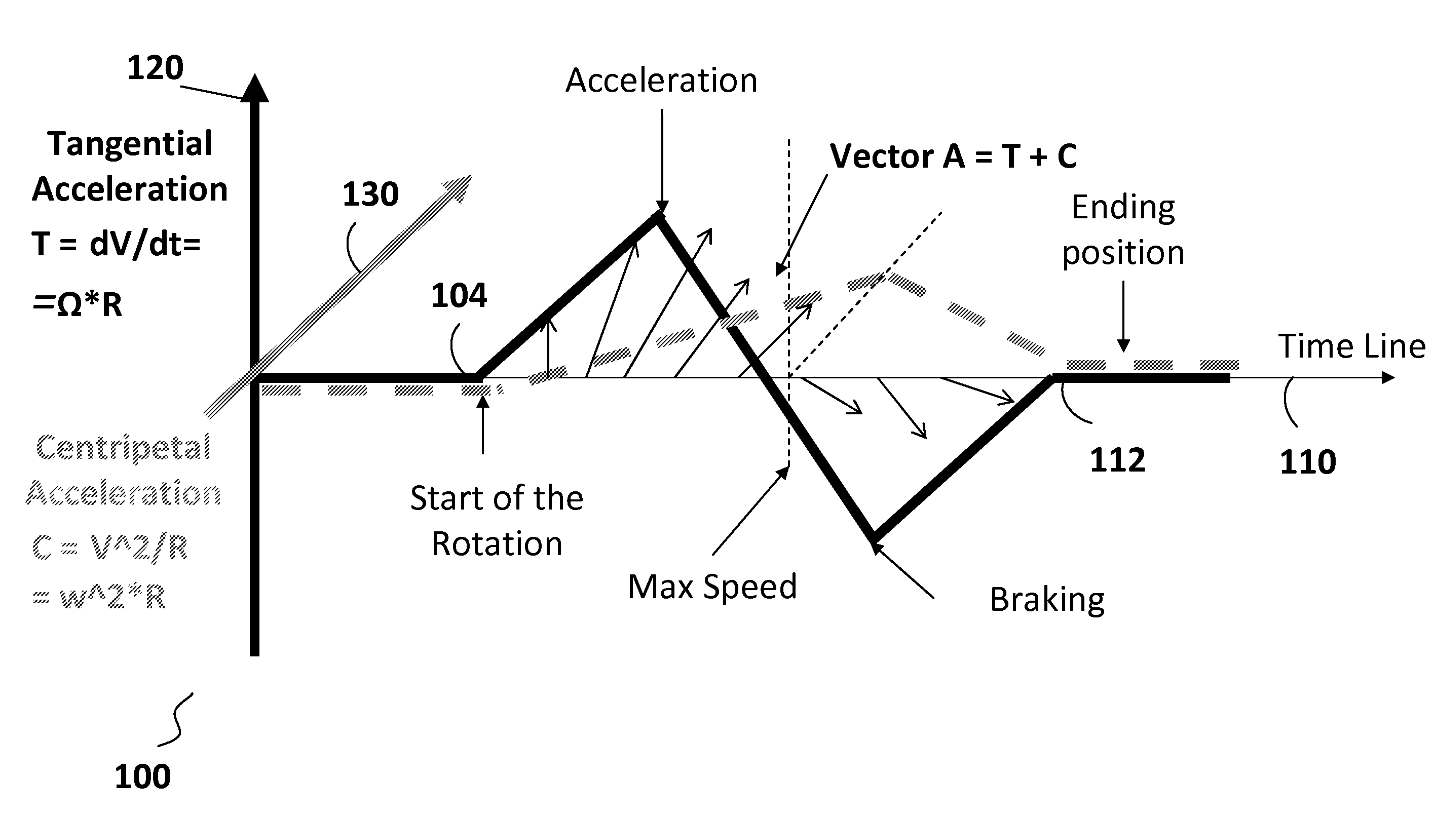
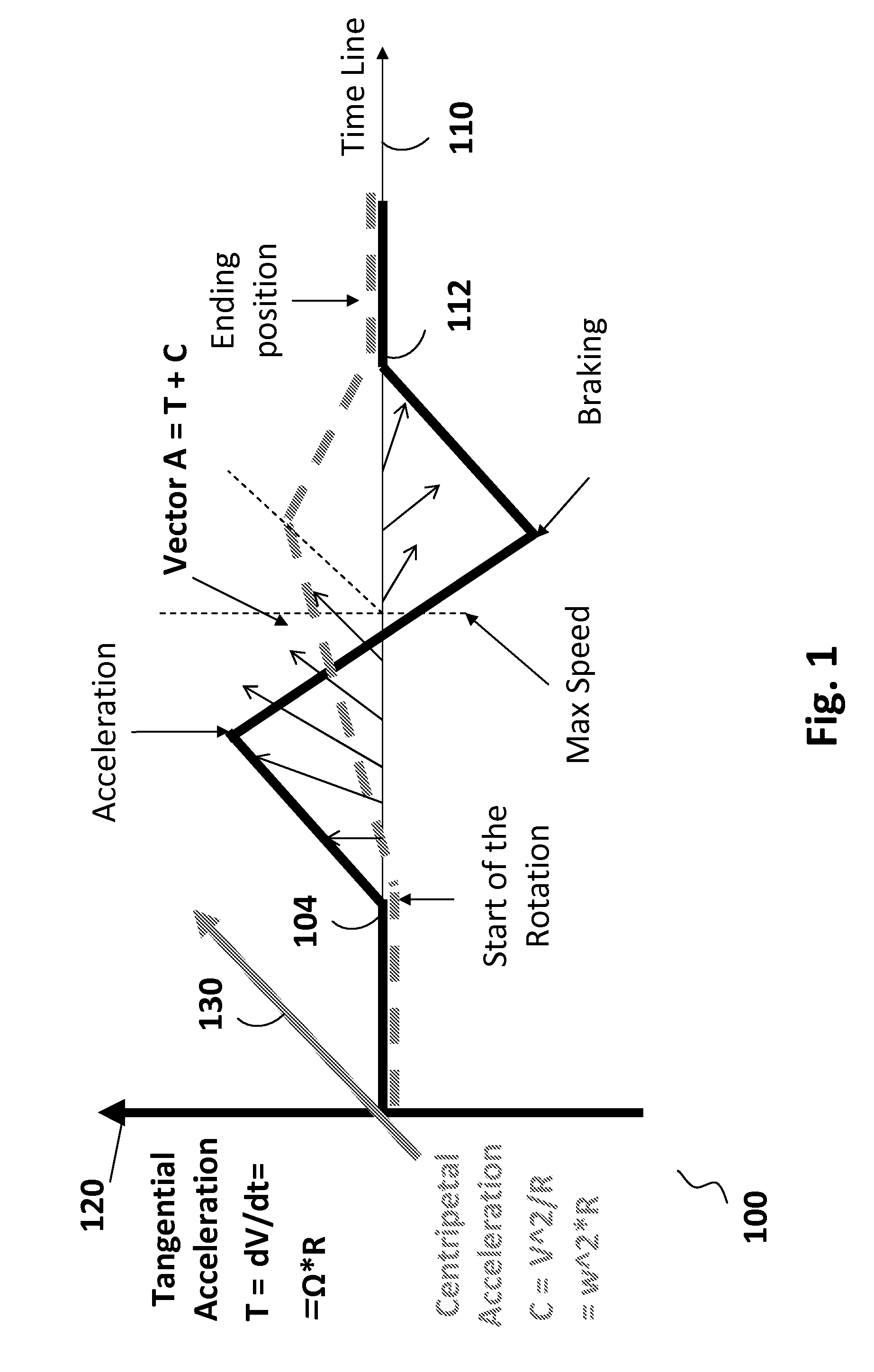
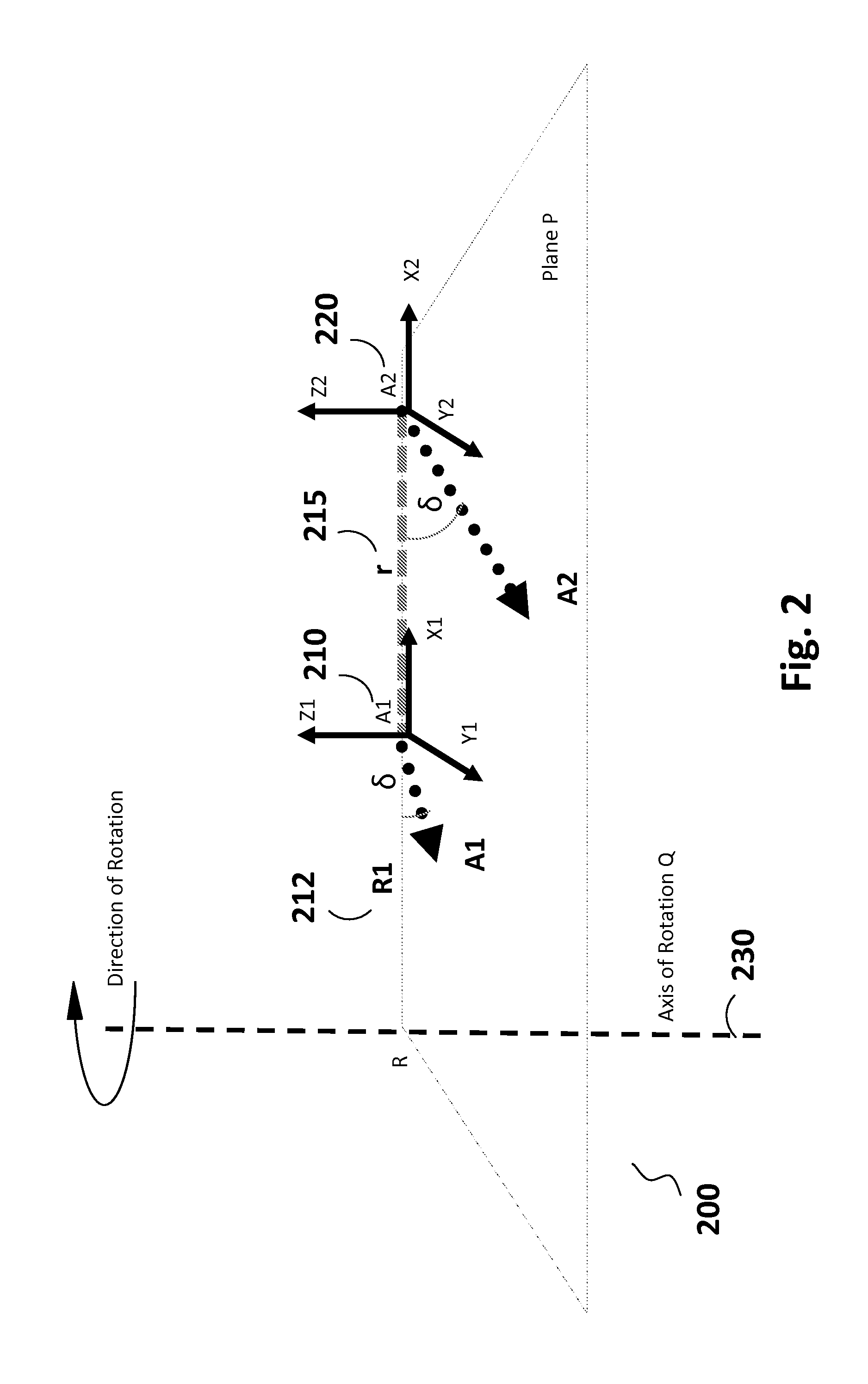
[0024]The present motion sensor system addresses the problem of gravity and motion interference by using a novel arrangement of two or more identical accelerometers with aligned sensitivity axes. Each of the accelerometers senses motion over at least two axes. The accelerometer readings include a component corresponding to gravitational force that is the same for each accelerometer in the arrangement. Taking the difference in accelerometer readings one can eliminate or reduce the gravitational interference and interference produced by external forces that are the same for each accelerometer in the system. Logic circuitry in communication with the accelerometer arrangement couples accelerometer signals to a processor to compute motion variables.

Technical Details

[0025]The varying arrangement of inertial motion sensors, i.e. accelerometers, and the data produced thereby are shown in details in the figures described below. In each of the figures below with their associated descr...


PUM


Abstract

An apparatus having an arrangement of two or more identical accelerometers with aligned sensitivity axes. Each of the accelerometers senses motion over at least one axis. The accelerometer readings include a component corresponding to gravitational force that is the same for each accelerometer in the arrangement. Logic circuitry in communication with the accelerometer arrangement couples accelerometer signals to a processor to compute motion variables.

Description

CROSS REFERENCE TO RELATED APPLICATION(S)[0001]This is a non-provisional utility patent application claiming benefit of the filing dates of U.S. provisional patent application Ser. No. 60 / 911,745, filed Apr. 13, 2007, and titled “A Force Sensing Apparatus and Method to Determine the Radius of Rotation of a Moving Object”, and U.S. provisional patent application Ser. No. 61 / 027,118, filed Feb. 8, 2008, and titled “A Force Sensing Apparatus and Method to Determine the Radius of Rotation of a Moving Object”, both of which are hereby incorporated by reference.FIELD OF THE INVENTION [0002]The invention discloses an apparatus that detects rotational and translational movement of a device that corresponds to motion input. An arrangement of two or more accelerometers is integrated into the device, wherein the accelerometers are separated in space and have aligned sensitivity axes. Logic circuitry in communication with the arrangement of the accelerometers couples accelerometer signals to a ...

Claims


Application Information

Patent Timeline
IPC IPC(8): G01P15/00G01C21/00
CPCG01C21/165G01P15/00G06F1/1626G06F1/1684G06F2200/1637G01P15/18G01P15/08
Inventor SHKOLNIKOV, MARK
Owner KEYNETIK
Why Eureka
Try Eureka