Apparatus for Lifting Presser Foot of Embroidery Machine

a technology of embroidery machine and presser foot, which is applied in the field of embroidery machines, can solve the problems of difficulty in adjusting the height of the presser foot, and achieve the effect of easy replacement of a sewing material or a sewing fram

Inactive Publication Date: 2008-10-23
SUSR PRECISION CO LTD
View PDF5 Cites 19 Cited by
  • Summary
  • Abstract
  • Description
  • Claims
  • Application Information

AI Technical Summary

Benefits of technology

[0016]Another object of the present invention is to provide an apparatus for lifting a presser foot of an embroidery machine, which easily replaces a sewing material or a sewing frame when replaced.

Problems solved by technology

At this time, it is difficult to adjust the height at which the presser foot 5 is placed on the sewing material because it is bent in a stepped shape at a predetermined length when viewed overall.

Method used


Image

  • Apparatus for Lifting Presser Foot of Embroidery Machine
  • Apparatus for Lifting Presser Foot of Embroidery Machine
  • Apparatus for Lifting Presser Foot of Embroidery Machine

Examples


Embodiment Construction

[0032]Reference will now be made in greater detail to an apparatus for lifting the presser foot of an embroidery machine according to an exemplary embodiment of the invention with reference to the accompanying drawings. Wherever possible, the same reference numerals will be used throughout the drawings and the description to refer to the same or like parts.

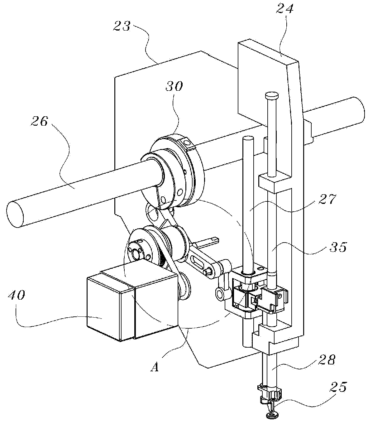
[0033]FIG. 3A is a perspective view illustrating the state in which an apparatus for lifting the presser foot of an embroidery machine according to an exemplary embodiment of the present invention is installed, and FIG. 3B is an enlarged view illustrating part “A” of FIG. 3A. FIG. 4 is an exploded perspective view illustrating an apparatus for lifting the presser foot of an embroidery machine according to an exemplary embodiment of the present invention.

[0034]Further, FIG. 5A is a partial perspective view illustrating the state in which an apparatus for lifting the presser foot of an embroidery machine according to an exemplary em...


PUM


Abstract

An apparatus for lifting the presser foot of an embroidery machine includes an arm having an upper shaft providing a driving force, a presser foot driving cam mounted on the upper shaft, a transmission member coupled to the presser foot driving cam and making an oscillating motion, a presser foot driving lever connected to the transmission member and pivoting around a predetermined pivoting point thereof in a vertical direction, a presser foot driving block reciprocating along a needle bar guide shaft according to an amount that the presser foot driving lever is pivoted and moving the presser foot in a vertical direction, and a presser foot height adjustor, displacing the pivoting point of the presser foot driving lever to adjust a height of the presser foot.

Description

BACKGROUND OF THE INVENTION[0001]1. Field of the Invention[0002]The present invention relates, in general, to an embroidery machine and, more particularly, to an apparatus for lifting the presser foot of an embroidery machine.[0003]2. Description of the Related Art[0004]Generally, an embroidery machine is a biaxial positioning control machine in which an embroidery stitch frame for fixing fabric undergoes horizontal motion in x-axis and y-axis directions while a needle bar thereof moves up and down.[0005]Since this embroidery machine does needlework while the embroidery stitch frame fixing the fabric is transferred in x-axis and y-axis directions, the precise and constant-speed movement of the embroidery frame has a close relationship to the quality of an embroidered pattern.[0006]Thus, as a source of power for driving the needle bar of the embroidery machine in a vertical direction, a servo motor, an induction motor capable of controlling speed, or the like is used. As the power so...

Claims


Application Information

Patent Timeline
Patent Type & Authority Applications(United States)
IPC IPC(8): D05B29/12
CPCD05B29/02D05C9/02D05C9/20D05B29/00D05C9/00
Inventor PARK, CHAN SOO
Owner SUSR PRECISION CO LTD
Why Eureka
Try Eureka