
Fluid Delivery Device With Flow Rate Control

a flow rate control and flow rate technology, applied in water supply installation, process and machine control, instruments, etc., can solve the problems of inherently inaccurate delivery system, less portable and more expensive than other types of pumps, and inability to accurately control the flow rate of the flow rate,

Inactive Publication Date: 2008-10-23
MICROLIN
View PDF3 Cites 28 Cited by
  • Summary
  • Abstract
  • Description
  • Claims
  • Application Information

AI Technical Summary

Benefits of technology

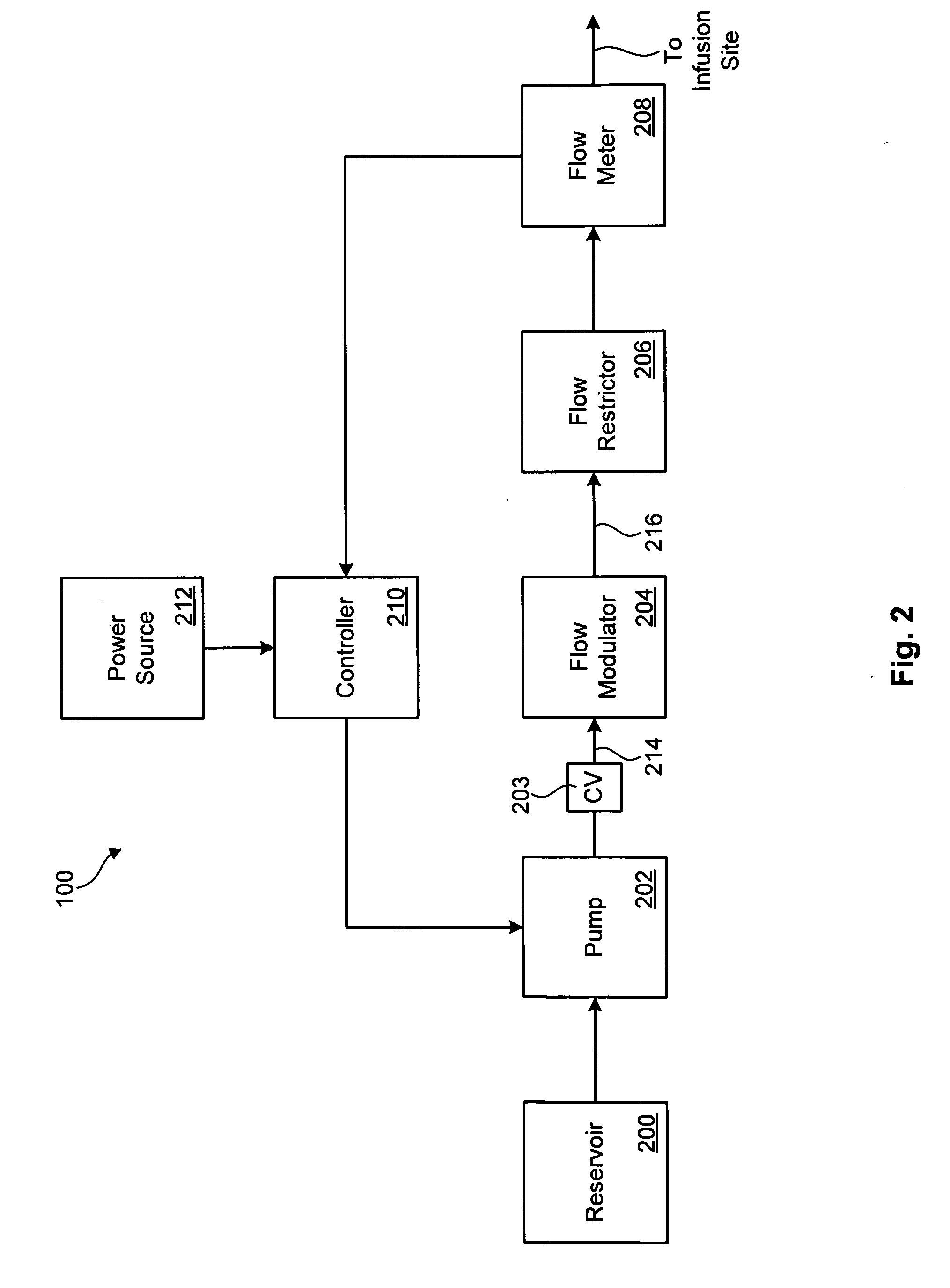
[0011]The flow modulator may smooth out irregularities in the flow rate, thereby generating a second fluid stream having a second flow rate that is substantially more uniform than the first flow rate. In certain embodiments, the flow modulator may include a volume expansion zone to expand upon receiving the first fluid stream. The volume expansion zone may then contract to generate the second fluid stream.
[0017]In some embodiments, the method may further include preventing the first fluid stream from substantially reversing a direction of flow. In other embodiments, a flow restrictor may be provided to regulate a flow of the first or second fluid stream. A bypass valve may be provided to enable the first or second fluid stream to bypass a flow restrictor.

Problems solved by technology

This type of delivery system, while inexpensive to manufacture and implement, is inherently inaccurate.
Such pumps, however, tend to be less portable and more expensive than other types of pumps.
Moreover, because delivery rate is calculated indirectly according to the revolution rate of the rotor, inaccuracies may occur.
Conventional diaphragm-type pumps, piezo pumps, or elastomeric balloon-type pumps, may provide a low-cost alternative for providing effective drug delivery, however, delivery rates effectuated by such pumps are subject to fluctuations caused by variations in liquid viscosity due to temperature, as well as variations in head backpressure.

Method used


Image

  • Fluid Delivery Device With Flow Rate Control
  • Fluid Delivery Device With Flow Rate Control
  • Fluid Delivery Device With Flow Rate Control

Examples


Embodiment Construction

[0031]It will be readily understood that the components of the present invention, as generally described and illustrated in the Figures herein, could be arranged and designed in a wide variety of different configurations. Thus, the following more detailed description of the embodiments of the invention, as represented in the Figures, is not intended to limit the scope of the invention, as claimed, but is merely representative of certain examples of presently contemplated embodiments in accordance with the invention.

[0032]Reference throughout this specification to features, advantages, or similar language does not imply that all of the features and advantages that may be realized with the present invention should be or are in any single embodiment of the invention. Rather, language referring to the features and advantages is understood to mean that a specific feature, advantage, or characteristic described in connection with an embodiment is included in at least one embodiment of the...


PUM


Abstract

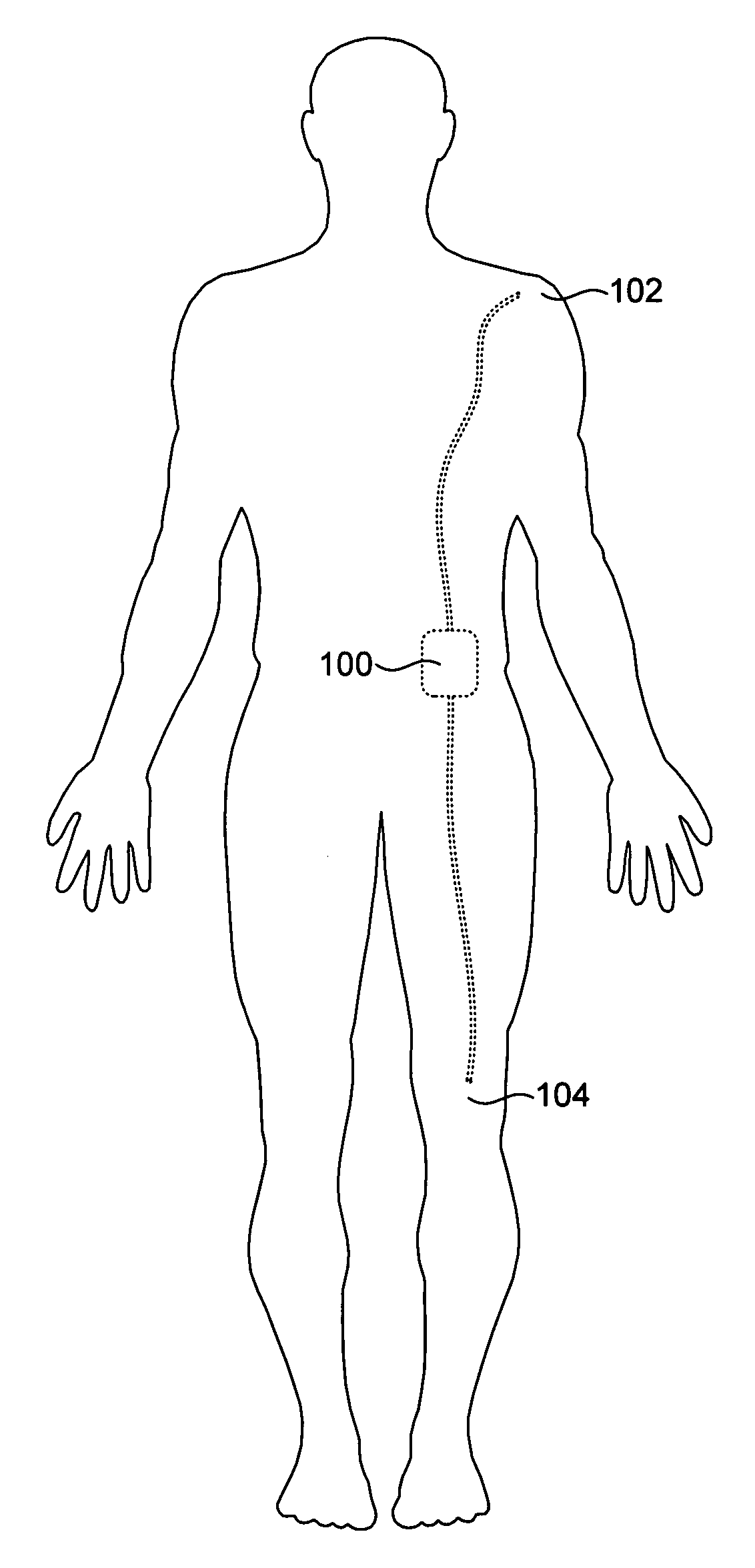
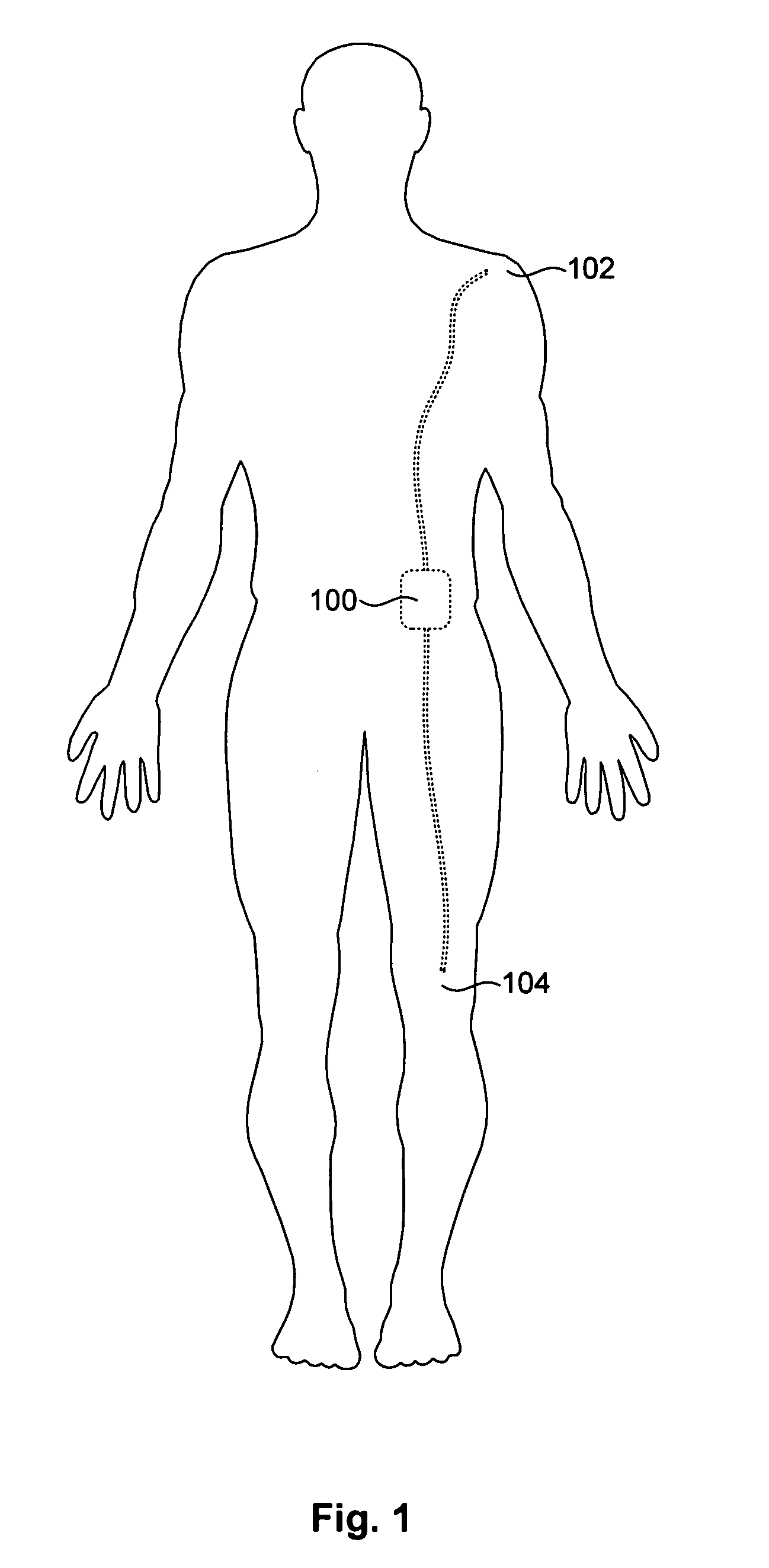
A device for delivering a fluid to a target site is disclosed in one embodiment of the invention as including a pump, a flow modulator, a flow meter, and a controller. The pump may generate a fluid stream characterized by a flow rate. The flow modulator may smooth out irregularities in the flow rate, thereby generating a second fluid stream having a second flow rate that is substantially more uniform than the first flow rate. The flow meter may measure the flow rate of the second fluid stream. The controller may then compare the flow rate of the second fluid stream to a target flow rate, and adjust the pump speed to substantially align the second flow rate with the target flow rate.

Description

CROSS-REFERENCE TO RELATED APPLICATION[0001]This application claims the benefit of U.S. Provisional Patent Application No. 60 / 912,463 filed Apr. 18, 2007, which application is incorporated by reference.FIELD OF THE INVENTION[0002]This invention relates to fluid delivery systems, and more particularly to systems and methods for delivering a fluid to a target location at a substantially uniform delivery rate.BACKGROUND[0003]Escalating costs of health care and advances in laparoscopic and other surgical techniques have encouraged minimally invasive surgical procedures with short associated recovery times. To facilitate early patient discharge while providing adequate post-operative pain management, portable drug delivery systems for in-home use are commonly prescribed following surgery.[0004]A portable drug delivery system may continuously infuse pain-relieving drugs into the patient at a predetermined basal rate, usually ranging between about three and about ten milliliters per hour, ...

Claims


Application Information

Patent Timeline
IPC IPC(8): F17D3/18F17D3/01F17D1/00A61M31/00A61M1/00
CPCA61M5/14244A61M5/16877A61M5/16886A61M2205/0294A61M2205/3368Y10T137/0357Y10T137/0318Y10T137/3149Y10T137/8158Y10T137/2562
Inventor GORDON, JOHN HOWARD
Owner MICROLIN
Learn More