Touch sensor switch

a technology of touch sensor and switch, which is applied in the direction of contact mechanism, emergency connection, pulse technique, etc., can solve the problems of productivity, cost reduction, and inability to enhance reliability, and achieve the effect of easy removal of the output of the touch sensor and high reliability

Inactive Publication Date: 2008-10-23
KK TOKAI RIKA DENKI SEISAKUSHO
View PDF4 Cites 25 Cited by
  • Summary
  • Abstract
  • Description
  • Claims
  • Application Information

AI Technical Summary

Benefits of technology

[0031]According to the preferred embodiment of the present invention, it is p...

Problems solved by technology

However, in the conventional switch comprising the touch sensor, since the harness is used for the connection between the conductive film and the wiring pattern of the board, metal fatigue progresses in accordance with an increase in usage frequency of the push-button or a stroke level of the harness.
Since the harness is easily broken, it is not possible to enhance the reliability.
Further, there are problems...

Method used


Image

  • Touch sensor switch
  • Touch sensor switch
  • Touch sensor switch

Examples


Embodiment Construction

[0039]Next, preferred embodiments according to the present invention will be explained in conjunction with appended drawings.

The First Preferred Embodiment

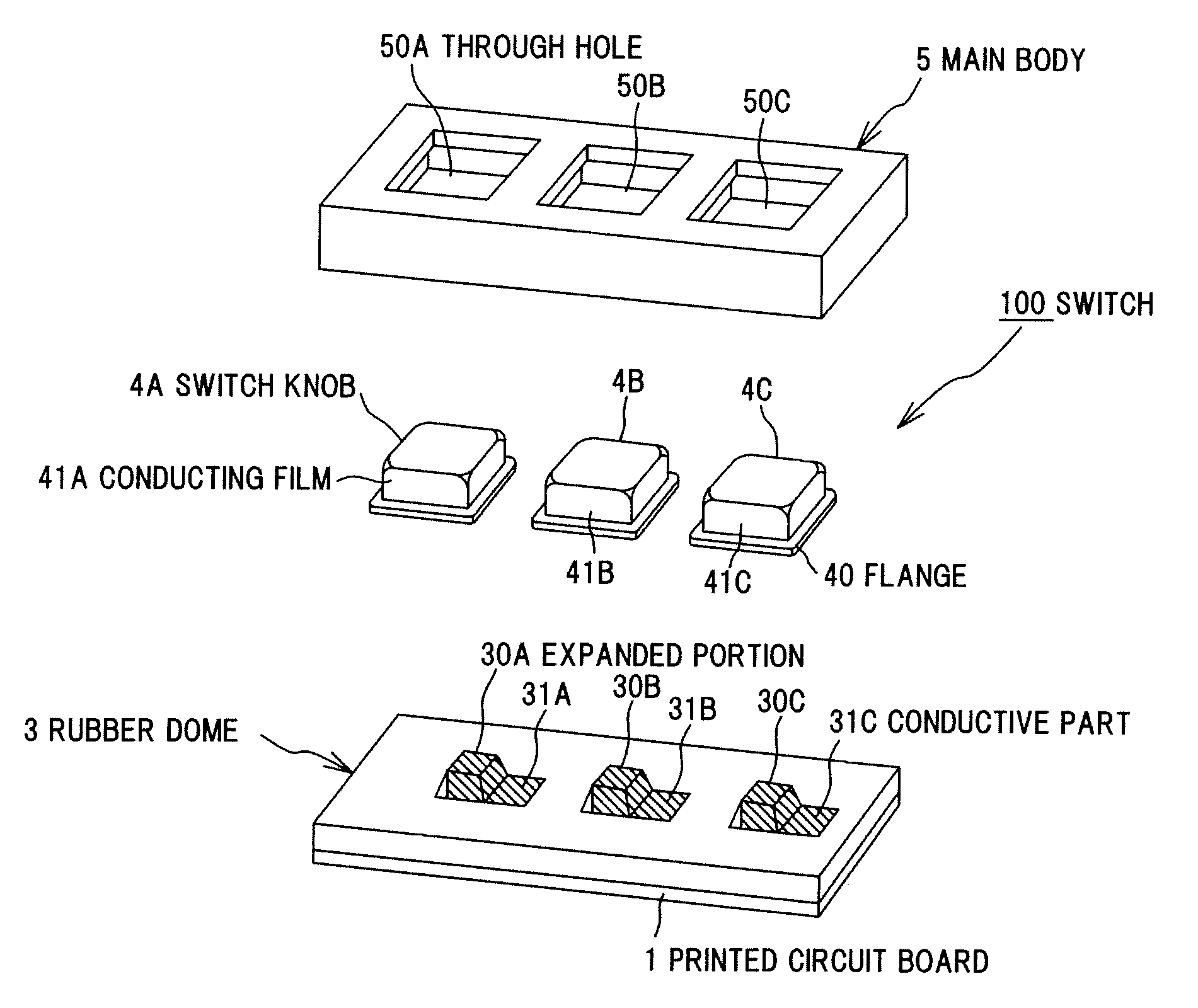
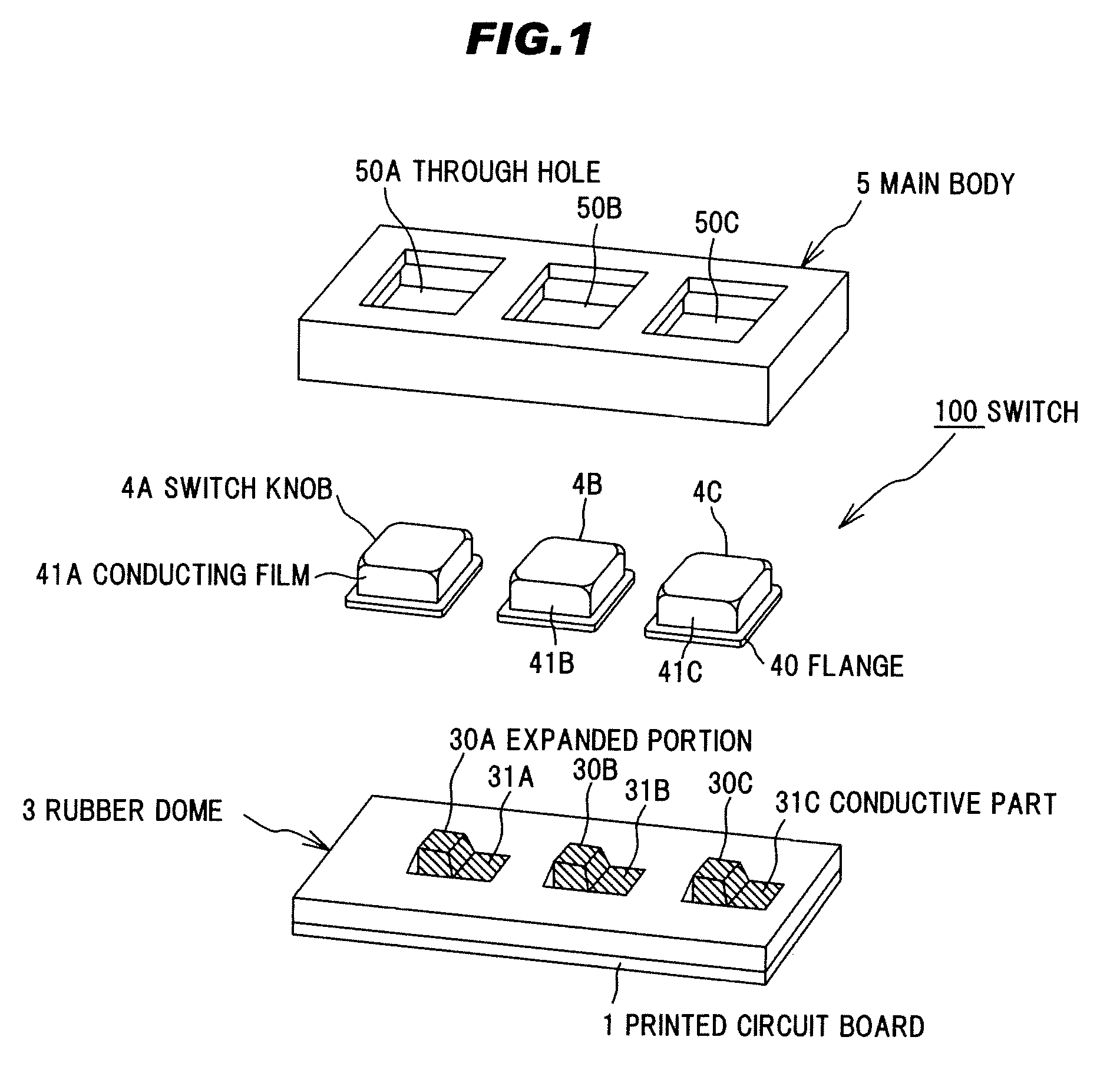
[0040]FIG. 1 is an exploded perspective view of a touch sensor switch in a preferred embodiment according to the present invention.

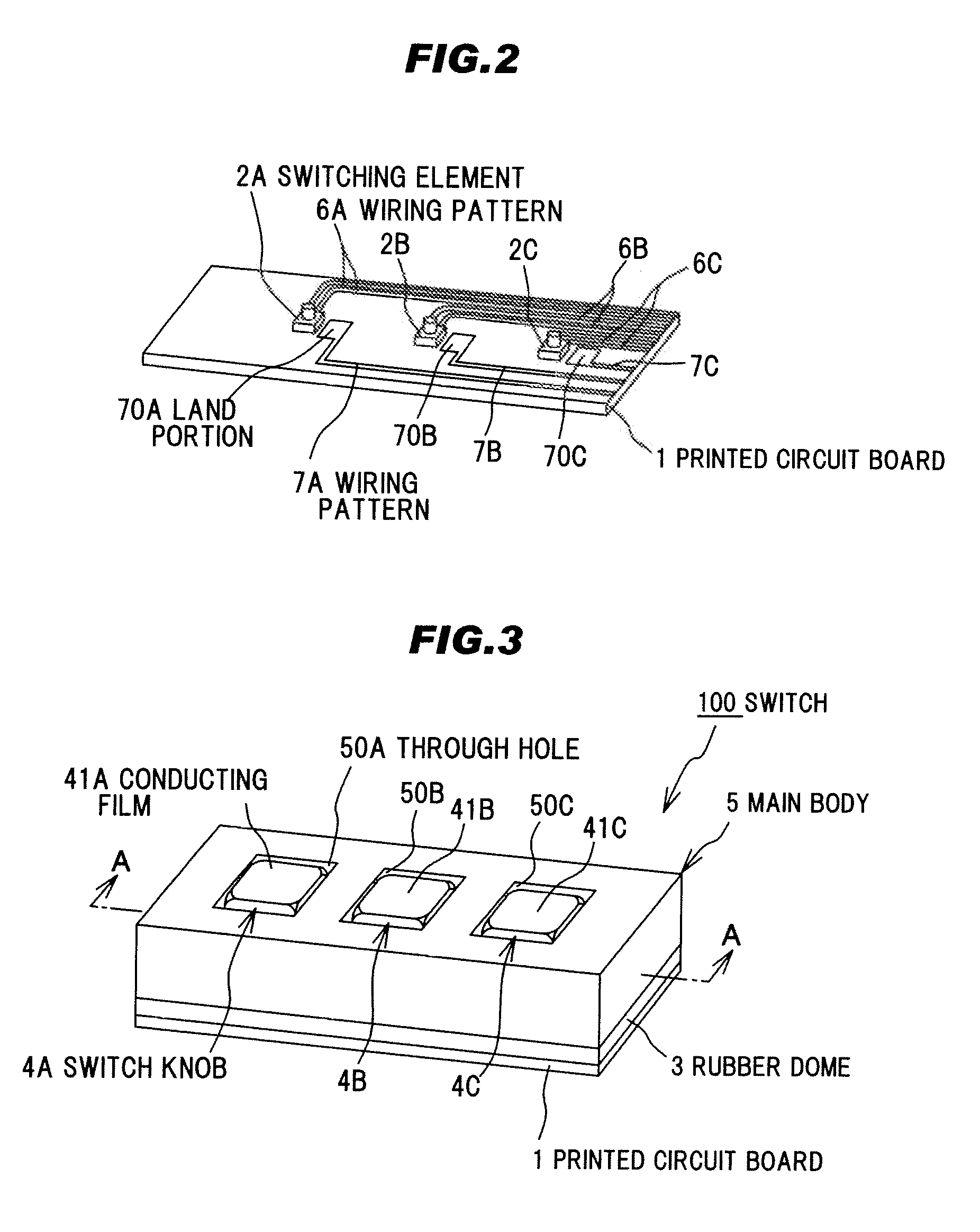
[0041]FIG. 2 is a perspective view showing a structure on a printed circuit board shown in FIG. 1.

[0042]FIG. 3 is a perspective view showing a finished state of the switch shown in FIG. 1.

[0043]FIG. 4 is a cross sectional view along A-A line of the switch shown in FIG. 3.

(Structure of the Switch)

[0044]As shown in FIG. 1, a switch 100 comprises a printed circuit board 1 having a rectangular shape, switching elements 2A, 2B, and 2C mounted on the printed circuit board 1 (as shown in FIG. 2), a rubber dome 3 provided on the printed circuit board 1 and comprising expanded portions 30A, 30B, and 30C for housing the switching elements 2A, 2B, and 2C, switch knobs 4A, 4B, and 4C provided with conductive films...


PUM


Abstract

A touch sensor switch for easily taking out an output of a touch sensor with high reliability. Push-type switching elements 2A, 2B, and 2C are mounted on a printed circuit board 1, a rubber dome 3 is provided with expanded portions 30A, 30B, and 30C for housing the switching elements 2A, 2B, and 2C, the switching elements 2A, 2B, and 2C are provided with conductive films 41A, 41B, and 41C on an outer surface and a lower face, conductive parts 31A, 31B, and 31C are provided at a conductive part such as an upper surface of the expanded portions 30A, 30B, and 30C of the rubber dome 3, or a wiring pattern of the printed circuit board 1, and the conductive films 41A, 41B, and 41C contact with the conductive parts 31A, 31B, and 31C constantly by a biasing force of the switching elements 2A, 2B, and 2C regardless the operation of switch knobs 4A, 4B, and 4C.

Description

[0001]The present application is based on Japanese Patent Application No. 2007-113118 filed on Apr. 23, 2007, the entire contents of which are incorporated herein by reference.BACKGROUND OF THE INVENTION[0002]1. Field of the Invention[0003]The present invention relates to a touch sensor switch.[0004]2. Related Art[0005]In vehicles, for example, switches each comprising a push-button or a touch sensor for starting and stopping of an operation of a mounted electronic device or an engine are used.[0006]As one example of a conventional switch using the touch sensor, JP-A-7-272604 discloses a switch in which a conductive touch portion is provided on a surface of a tile, a touch sensor circuit is provided on a back side of the tile, the touch sensor circuit and the touch portion are connected to each other by a conductive rubber or a lead wire, and the touch sensor circuit detects an electrical alteration when a finger contacts with the touch portion to conduct an ON / OFF operation, has be...

Claims


Application Information

Patent Timeline
IPC IPC(8): H03K17/975
CPCH01H13/70H01H13/81H01H2003/0293H01H2207/002H01H2229/046H03K17/975H03K2217/96054
Inventor MURASE, KEIJIMURASE, SEIYAMIYATA, MASAHIKOKUMAGAI, KATSUHIDEIWASAKI, KENJIYAMAGUCHI, KAZUKI
Owner KK TOKAI RIKA DENKI SEISAKUSHO
Why Eureka
Try Eureka