
Aeronautical satellite TV repeater

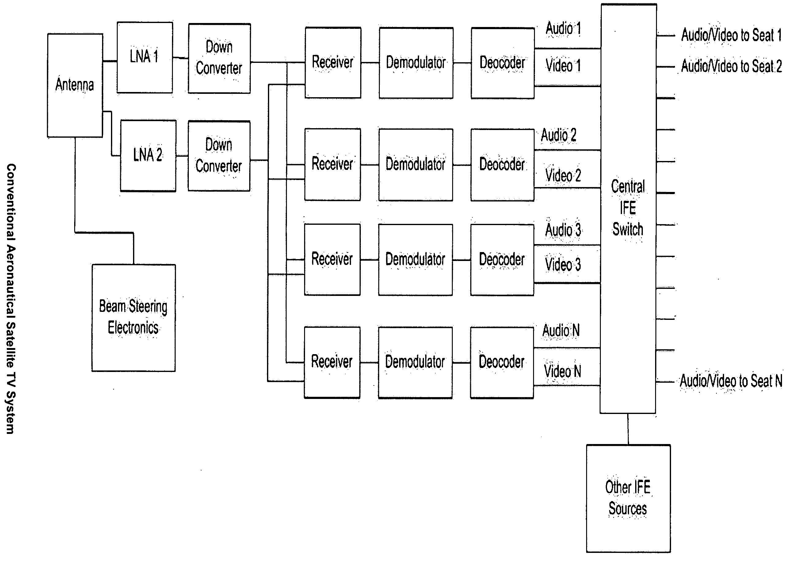
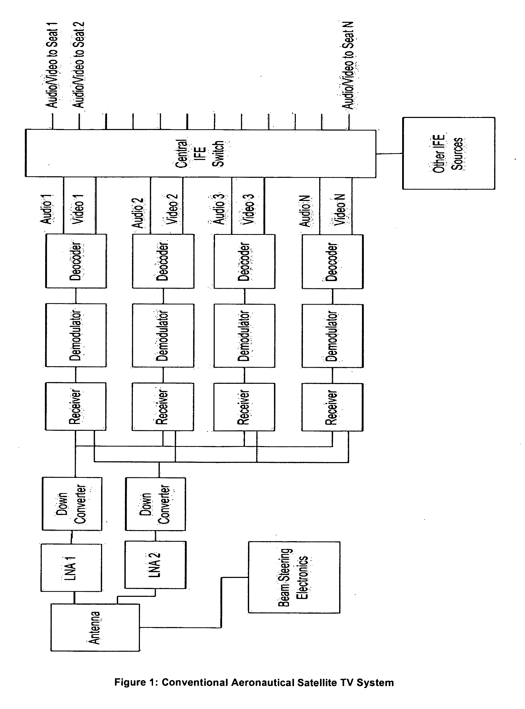
a technology for aeronautical satellites and repeaters, which is applied in the field of aeronautical satellite tv repeaters, can solve the problems of otherwise useless receivers in aircra

Inactive Publication Date: 2008-10-23
EMS TECH CANADA
View PDF16 Cites 7 Cited by
  • Summary
  • Abstract
  • Description
  • Claims
  • Application Information

AI Technical Summary

Benefits of technology

"The invention is a new and lower cost aeronautical satellite television system for aircraft that allows for the use of lower cost and more compact components. The system uses a simple repeater to receive and amplify the satellite video broadcast, eliminating the need for a central location for demodulation and decoding. The system also utilizes terrestrial hand-held and portable video receivers that are commonly available, but are typically not used on aircraft due to the lack of infrastructure and the cost of the equipment. The invention provides a solution for making satellite TV available on all aircraft sizes and reduces the cost, weight, and complexity of signal distribution to the users."

Problems solved by technology

Such receivers are otherwise useless in an aircraft since the aircraft blocks the signals transmitted and is typically out of range of the terrestrial digital video networks.

Method used


Image

  • Aeronautical satellite TV repeater
  • Aeronautical satellite TV repeater
  • Aeronautical satellite TV repeater

Examples


Embodiment Construction

4.1 Simple Repeater

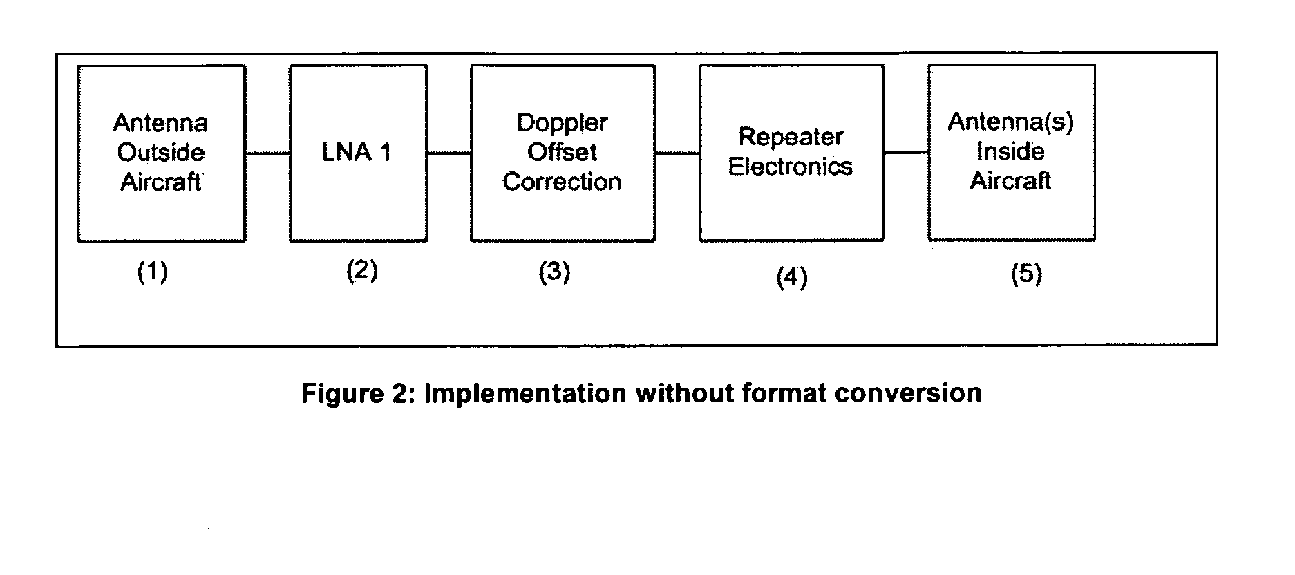
[0014]The simplest implementation of the proposed invention is shown in FIG. 2. In this simple configuration an antenna (1) on the outside of the aircraft receives a satellite video broadcast. This is then amplified by Low Noise Amplifier (2). The Doppler offset resulting from the relative motion of the aircraft relative to the satellite is eliminated by block (3). The repeater electronics (4) amplifies the signal and may incorporate electronics to control signal level, eliminate feedback and perform other monitoring, control, source selection, and content selection functions. The amplified signal is then retransmitted into the cabin interior by one or more antennas inside the aircraft (5). Either the repeater electronics (4) or the Doppler correction block (3) may, or may not, incorporate a frequency offset such that the signal frequency transmitted inside the aircraft is different from that transmitted by the satellite by some fixed amount. This offset could sim...


PUM


Abstract

A repeater for digital satellite television broadcasts wherein the repeater receives digital television signals broadcast from a satellite using one or more antennas mounted on the outside of an aircraft; the repeater corrects for Doppler frequency offset, resulting from the aircraft and / or satellite motion, prior to re-transmission of the broadcast into the interior of the airframe. This correction is a shift of the received signal frequency; the repeater re-transmits the broadcast, in a modulated and coded format, into the inside of an aircraft, the re-transmitted signal is received by multiple users inside the aircraft; the repeated signal is in a modulated and / or coded form and consequently the multiple users of the signal must each have a receiver capable of performing the required demodulation and / or decoding.

Description

RELATED APPLICATION DATA[0001]Pursuant to 35 U.S.C. 119(a), the instant application claims priority to prior European application number 07 105 972.9, filed Apr. 11, 2007.BACKGROUND OF THE INVENTION[0002]Aircraft have been receiving television signals transmitted from satellites for over a decade and such systems have become common and popular. These systems are very costly however and the invention described here provides a means of implementing much lower cost aeronautical satellite TV systems. In addition this invention provides a means of utilizing terrestrial hand-held and portable video receivers while on an aircraft. Such receivers are otherwise useless in an aircraft since the aircraft blocks the signals transmitted and is typically out of range of the terrestrial digital video networks.[0003]Conventional aeronautical satellite tv systems use large steered antennas on the outside of the aircraft to receive signals that are intended for receivers in homes on the ground. In 20...

Claims


Application Information

Patent Timeline
Patent Type & Authority Applications(United States)
IPC IPC(8): H04N7/20
CPCH04H20/02H04H20/62H04N7/20H04N21/2146H04N21/6143
Inventor HEBB, GARYSTRICKLAND, PETER
Owner EMS TECH CANADA
Learn More