
Motor-driven saber saw with guide device

Active Publication Date: 2008-10-30
HILTI AG
View PDF17 Cites 5 Cited by
  • Summary
  • Abstract
  • Description
  • Claims
  • Application Information

AI Technical Summary

Benefits of technology

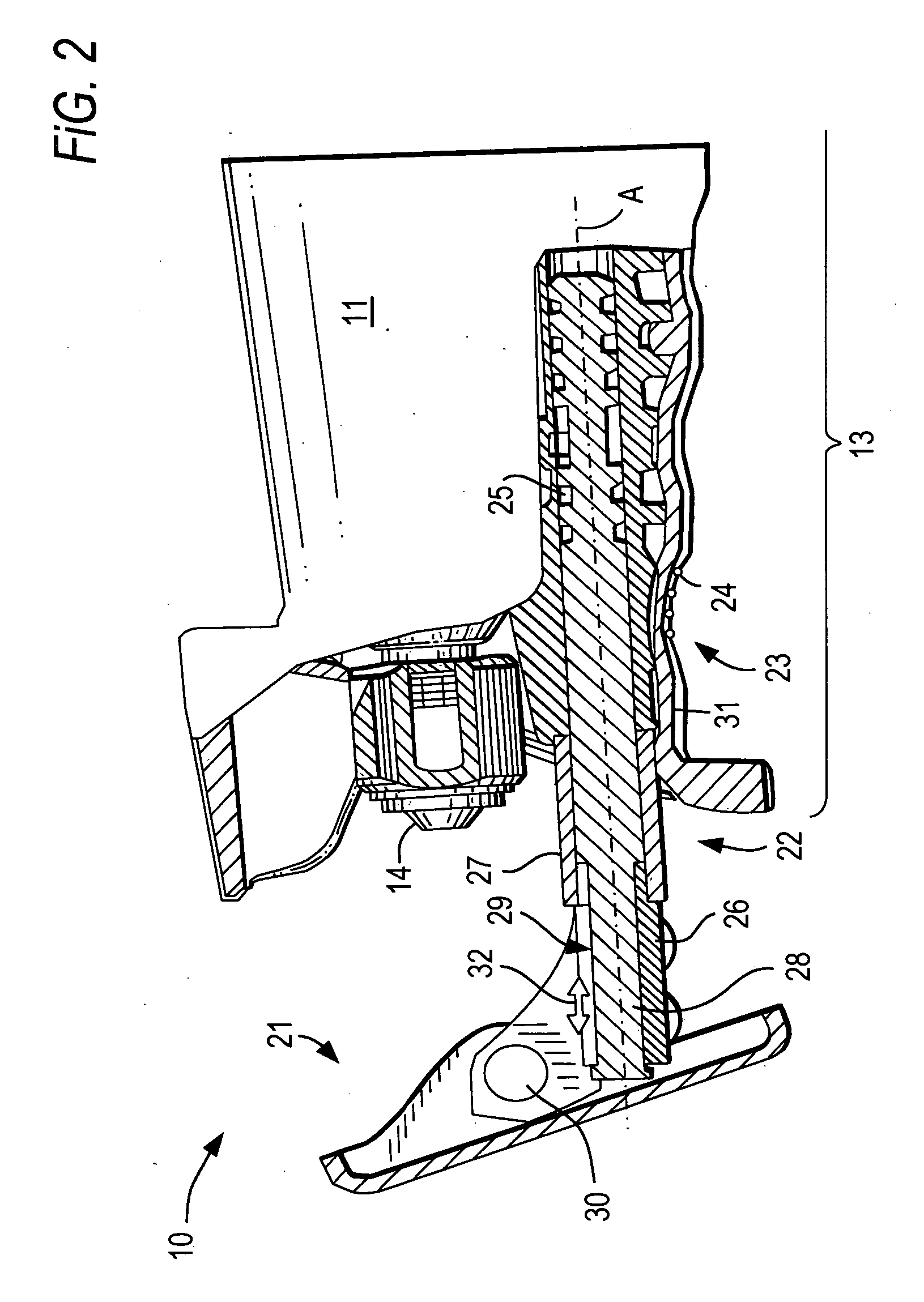
[0009]This and other objects of the present invention, which will become apparent hereinafter, are achieved by providing a saber saw in which the guide element is supported on the at least one connection part for displacement along an axis, and the guide device further includes at least one spring element located between the at least one connection part and the guide element. The spring element absorbs the rapidly increasing accelerations and damps a further transmission of vibrations and impacts.
[0010]Advantageously, the at least one spring element is formed as an elastomeric sleeve. This provides, in addition to separation of vibrations, also for their damping, on one hand, and on the other hand, enables their cost-effective replacement.

Problems solved by technology

The drawback of the saber saw discussed above consists in that the vibration, which act on the guide shoe during an operation of the saber saw, are transmitted to the saw neck that functions as a hand-hold.

Method used


Image

  • Motor-driven saber saw with guide device
  • Motor-driven saber saw with guide device
  • Motor-driven saber saw with guide device

Examples


Embodiment Construction

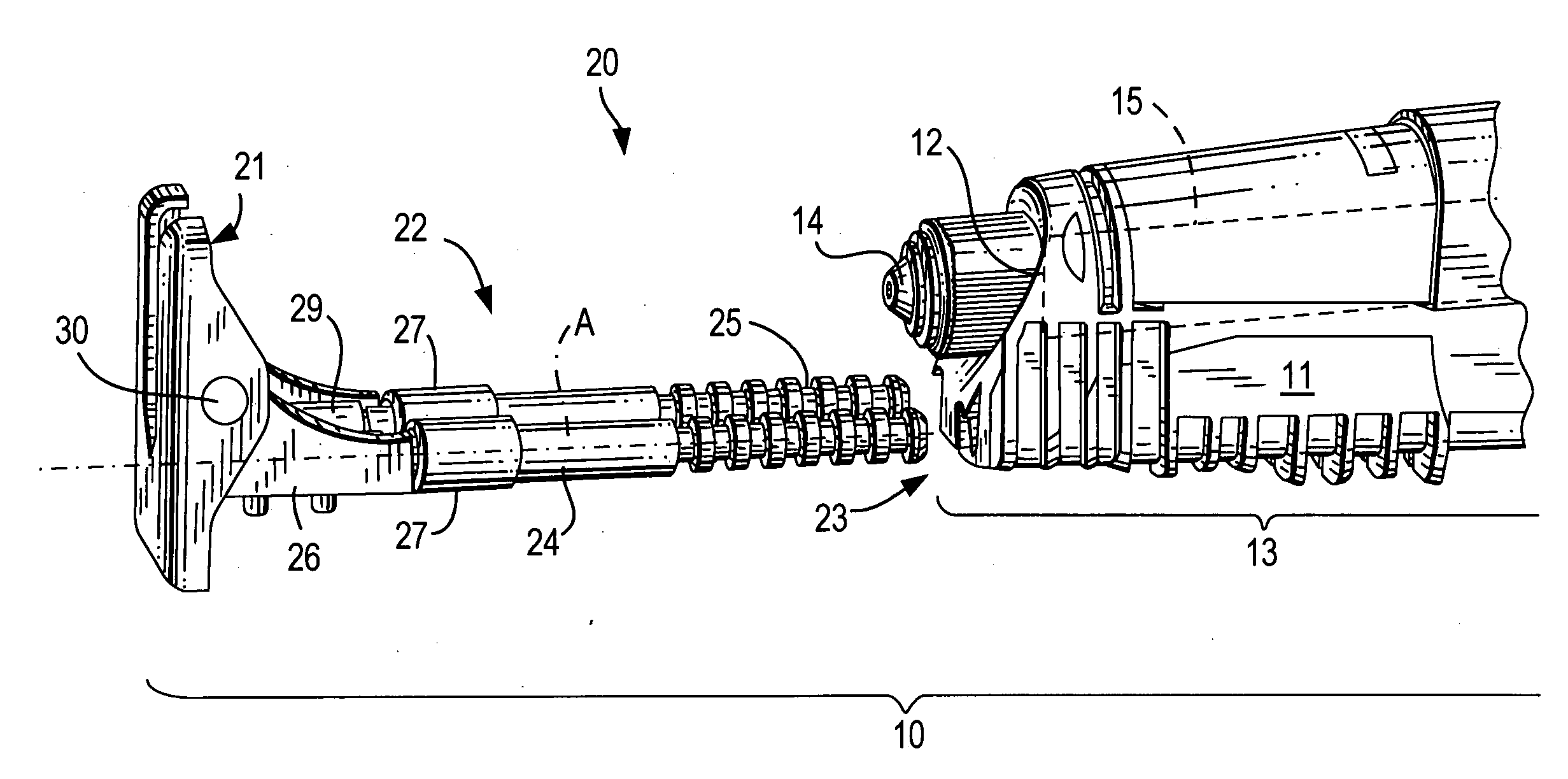
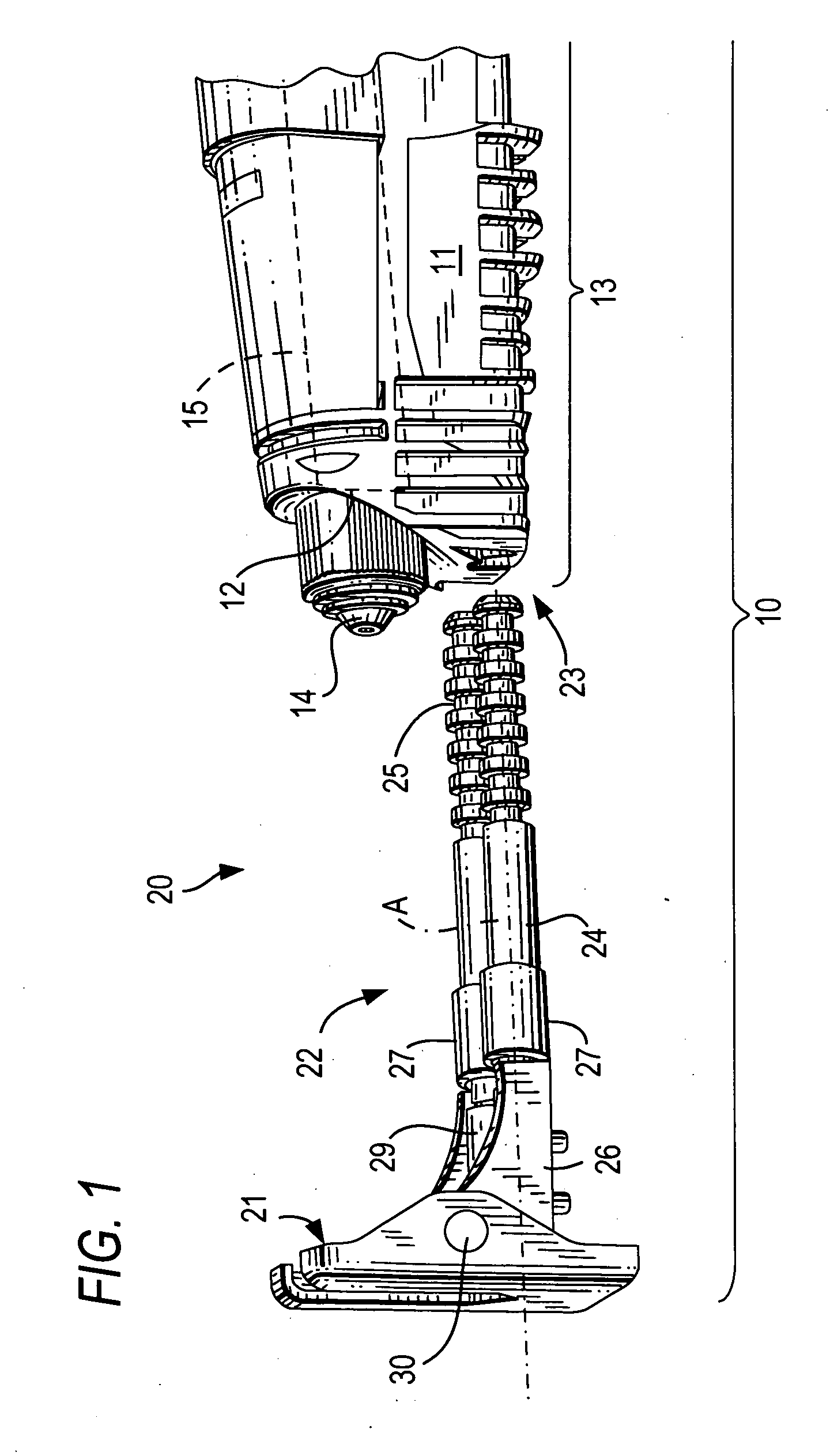
[0019]A motor-driven saber saw 10, a front, working tool-side portion of which is shown in FIGS. 1-2, has a housing 11 having, at its working tool end, a working tool opening 12 and a saw neck 13 which is formed next to the opening 12 and which serves during operation as a handhold. Because the saw neck 13 serves as a hand-hold during operation, it is surround, in an end-assembled condition, with a glove 31 (see FIG. 2) which is not shown in FIG. 1 for clarity sake. During operation, a working tool holder 14, which is mounted at a free end of a push rod 15, which is shown with a dash line, together with a secured thereon, saw blade, reciprocates through the opening 12.

[0020]FIG. 1 shows a saw blade guide device 20 separated from the housing 11 of the saw 10. The guide device 20 includes a guide element 21 in form of a guide shoe and a connecting device 22 which connects the guide device 20 to the housing 11. The connection device 22 can be inserted in a connection device receiving e...


PUM

PropertyMeasurementUnit
Displacementaaaaaaaaaa

Abstract

A motor-driven saber saw includes a guide device releasably connectable with the saw housing (11) in a region of the neck (13) and including a guide element (21) for guiding the saber saw (10) over a workpiece, a connection device (22) for connecting the guide element (21) to the housing (11) and having at least one connection part extending along an axis (A) and connectable with the neck (13), with the guide element (21) being supported on the at least one connection part (24) for displacement along the axis (A), and with the guide device (20) further including at least one spring element (27) located between the at least one connection part (24) and the guide element (21).

Description

BACKGROUND OF THE INVENTION[0001]1. Field of the Invention[0002]The present invention relates to a motor-driven saber saw including a housing having a neck extending in a direction of a working tool holder, and a guide device releasably connectable with the housing in a region of the neck and having a guide element for guiding the saber saw over a workpiece, a connection device for connecting the guide element to the housing and having at least one connection part connectable with the neck.[0003]2. Description of the Prior Art[0004]In the saber saws of the type discussed above, the guide element, such as guide shoe or tubular adapter is used to provide for a reliable and precise guidance of a saber saw over a workpiece. During the operation of the saber saw, the guide element is pressed against the workpiece.[0005]U.S. Pat. No. 5,421,091 discloses a saber saw having a housing, a guide shoe for guiding the saber saw over a workpiece, and a motor-driven, in a pendulum-like manner, pus...

Claims


Application Information

Patent Timeline
IPC IPC(8): B23D49/16B23D51/00
CPCB23D51/02
Inventor HAAS, GUENTERLINK, BERNHARDSTEINGRUBER, ADRIANLANG, EBERHARD
Owner HILTI AG
Learn More