Airframe leading edge

a leading edge and aircraft technology, applied in the direction of fuselage, fuselage bulkheads, transportation and packaging, etc., can solve the problems of high risk of accident, collisions may occur, and heavy birds could damage the structure of the wing/fin/stabilizer/nacelle/nose, so as to save time and cost, save damage, and cost-effectively replace the

Inactive Publication Date: 2018-11-20
SAAB AB
View PDF22 Cites 3 Cited by
  • Summary
  • Abstract
  • Description
  • Claims
  • Application Information

AI Technical Summary

Benefits of technology

[0027]The joint suitably is a butt joint or preferably a scarf joint (a scarf joint having two mating inclined faces) comprising overlapping contact areas. By the present solution is achieved that the structural portion will be protected in the event of bird impact or eventual taxi into hangar door or other aircraft. By the deformation zone of the airframe leading edge part skin and the beforehand and predetermined set strength stress set of the breakable joint, the airframe leading edge will take up and convert impact forces affecting the skin of the airframe leading edge instead of the structural portion, with a risk for damaging the latter. The impact energy will be transferred into the “breakaway” force, breaking away the airframe leading edge from the structural portion. This is cost-effective in view of service and the structural portion remains intact and its structural properties are not affected. The structural portion must not be built with larger amount of material for reinforcing the structural portion. This saves weights and fuel, which is important for aircraft. By providing at least one of the longitudinal (in span wise direction) joint edges with said determined maximum joint strength (Pmax) and the other chordwise arranged joints with a higher strength for firm bonding, the airframe leading edge (in case of bird impact) will maintain its position in front of the structural portion, wherein it is adapted to resilient spring back to original position, thereby not affecting the air stream in an unacceptable way.
[0068]In such way time and costs are saved in case of an bird impact. The wing box will be saved from damage at the same time the leading edge part (which has been damaged) cost-effective can be replaced.

Problems solved by technology

Heavy birds could also damage the structure of the wing / fin / stabilizer / nacelle / nose in event of collision.
Such collisions may especially occur during takeoff and landing in bird-rich biotopes.
In such case the risk of accident is high.
The object impacting on the leading edge thus may cause large damage to the adjacent structure.
Also flying through hailstorm could negatively affect the leading edge and airframe structure.

Method used


Image

  • Airframe leading edge
  • Airframe leading edge
  • Airframe leading edge

Examples


first embodiment

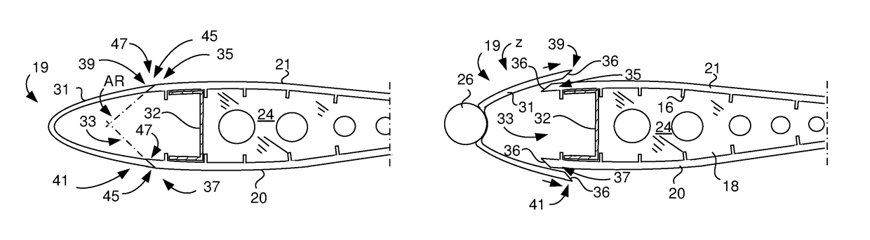
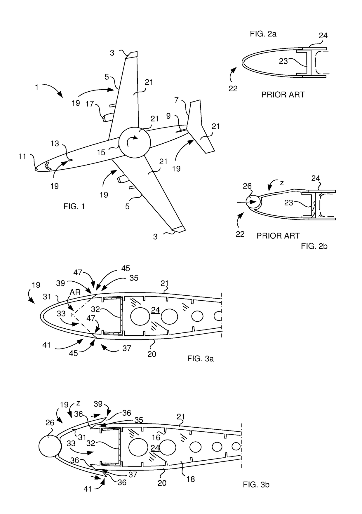
[0090]FIGS. 3a and 3b illustrate a cross-sectional view of an airframe leading edge part 19 comprising a leading edge skin 31 according to the present invention. The airframe leading edge part 19 is formed as a U-formed profile and is designed to be replaceable (removable) fixed to an upper 35 and lower 37 wing skin edge of a wing skin 20, 21 (lower and upper skin), which during use moves through the air. The wing skins 20, 21 are parts of a structural portion 33 comprising a U-beam 32, wing ribs 18 and stringers 16, all of which parts are constituting a so called wing box 24 of the wing. The airframe leading edge part 19 comprises a first 39 and a second 41 longitudinal joint edge, each of which is adapted to fit the respective wing skin edge 35, 37. The respective fit is made by joining each longitudinal joint edge 39, 41 to said corresponding wing skin edge 35, 37 via an adhesive 45 forming a joint 47 between the wing skin edge 35, 37 and said longitudinal joint edge 39, 41. The ...

second embodiment

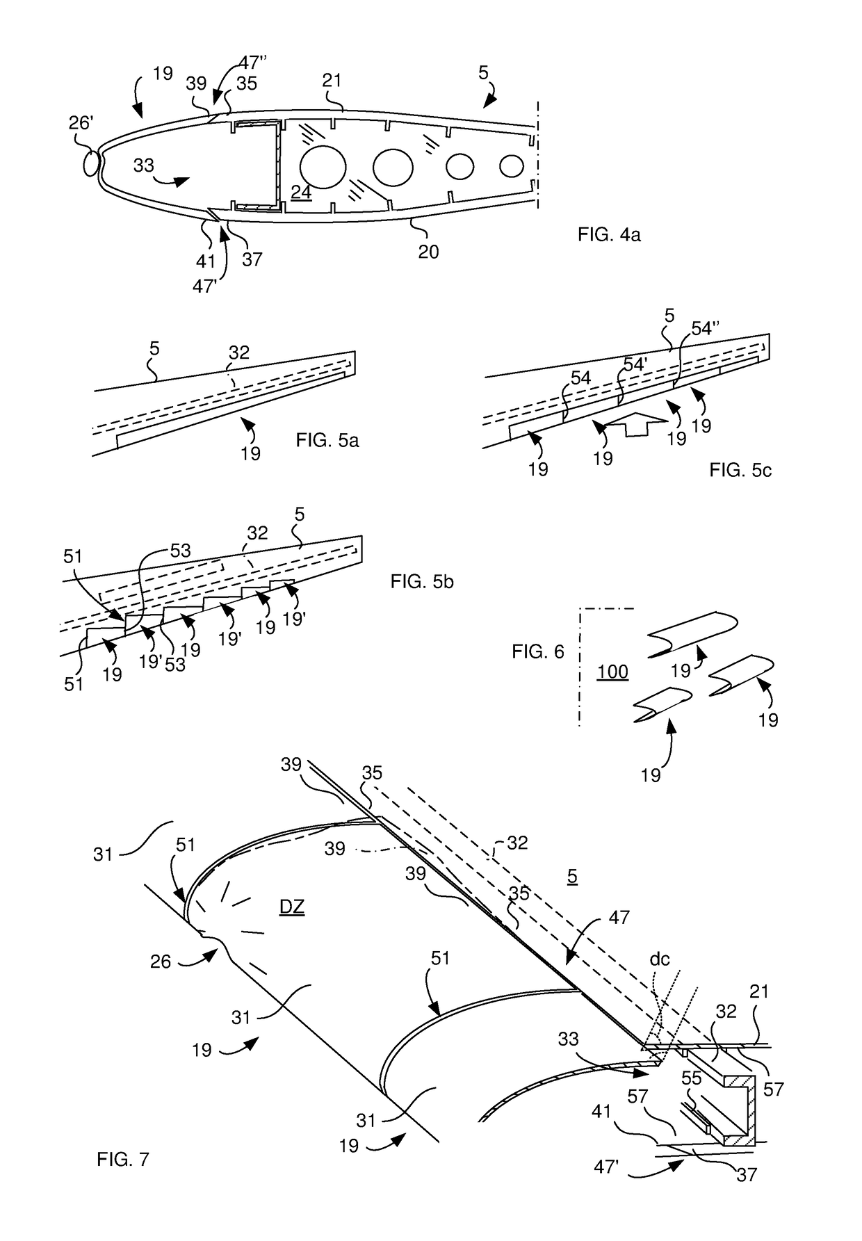
[0092]FIG. 4a schematically illustrates a cross-sectional view of an airframe leading edge part 19 according to a Only one joint (the lower 47′) is adapted to break in the event of foreign object 26′ impact. The joint 47′ is designed to break at a beforehand determined maximum joint strength (Pmax) of the joint's 47′ adhesive 45 (bonding together the wing skin edge 37 and joint edge 41 during normal use of the airframe) for protecting the wing box 24 and other structural wing parts, such as lower 20 and upper 21 skins of the wing 5, from breakage in case of said impact. The upper joint 47″ is firmly adhered to the structural portion's 33 upper wing skin edge 35 of the upper wing skin 21.

[0093]FIG. 4b schematically illustrates a portion of a leading edge part 19 mounted to a structural portion 33 including an upper composite skin 35. The leading edge part is made of metal and is bolted (bolts 14) to the skin 35. The area of the longitudinal joint edge comprises an outermost edge sec...

third embodiment

[0099]FIG. 5a schematically illustrates a wing 5 comprising an airframe leading edge part 19 being designed according to a The airframe leading edge part 19 is made in one piece for covering the wing's 5 edge facing the airflow.


PUM


Abstract

An airframe leading edge part designed to be replaceable fixed to a structural portion which during use moves through the air. The airframe leading edge part includes first and second longitudinal joint edges adapted to fit the structural portion. At least one joint is provided between the structural portion and at least one of the longitudinal joint edges. The joint is adapted to break in the event of a object strikes and deforms the airframe leading edge part during use. The joint is designed to break at beforehand determined maximum joint strength of the joint. Also a repair method for exchanging a damaged leading edge.

Description

CROSS-REFERENCE TO RELATED APPLICATIONS[0001]The application is the national phase under 35 U.S.C. § 371 of PCT / SE2012 / 051280 filed 20 Nov. 2012.TECHNICAL FIELD[0002]The present invention relates to an airframe leading edge and a method for repairing an airframe leading edge.[0003]The invention relates to the aircraft industry and to aircraft service engineering. The invention is not limited thereto, but could also be related to activities of airline companies as well.BACKGROUND ART[0004]Wings (also fins, stabilizer, nacelles, nose cones etc.) of aircraft comprise airframe leading edges. The leading edge is often made as an one-piece member or multi-piece members, which can be designed to be removable or cut from the wing and exchanged with a new airframe leading edge bonded or bolted to the wing box structure. Such exchange is made if the aircraft has collided with a bird, or in case of ground accidents, wherein the air frame leading edge has been damaged or buckled. Heavy birds co...

Claims


Application Information

Patent Timeline
Patent Type & Authority Patents(United States)
IPC IPC(8): B64C1/06B64C3/28B64C1/12B64D45/00
CPCB64C1/062B64C3/28B64C1/12B64D2045/0095
Inventor NORDIN, PONTUSSTRINDBERG, GOTE
Owner SAAB AB
Why Eureka
Try Eureka