Rod coupling having a sacrificial element

a technology of sacrificial element and coupling, which is applied in the direction of couplings, borehole/well accessories, manufacturing tools, etc., can solve problems such as considerable forces, and achieve the effect of lowering costs

Inactive Publication Date: 2015-02-03
TRACTO TECHN
View PDF36 Cites 3 Cited by
  • Summary
  • Abstract
  • Description
  • Claims
  • Application Information

AI Technical Summary

Benefits of technology

[0011]Against this background, the invention is based on the object to provide a novel connection system for connecting ho

Problems solved by technology

During operation of the rod assemblies, considerable forces occur.
If there is

Method used


Image

  • Rod coupling having a sacrificial element
  • Rod coupling having a sacrificial element
  • Rod coupling having a sacrificial element

Examples


Embodiment Construction

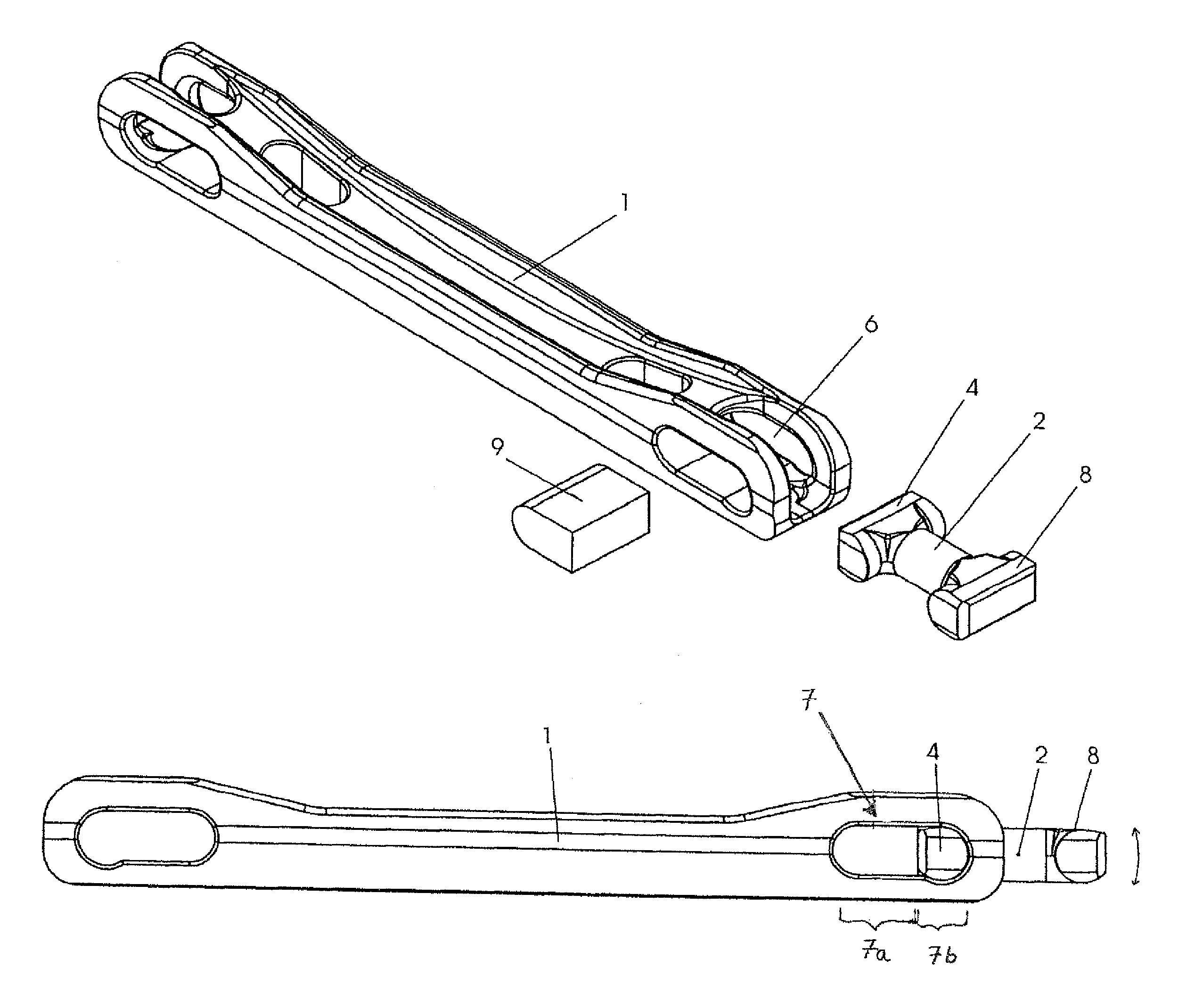
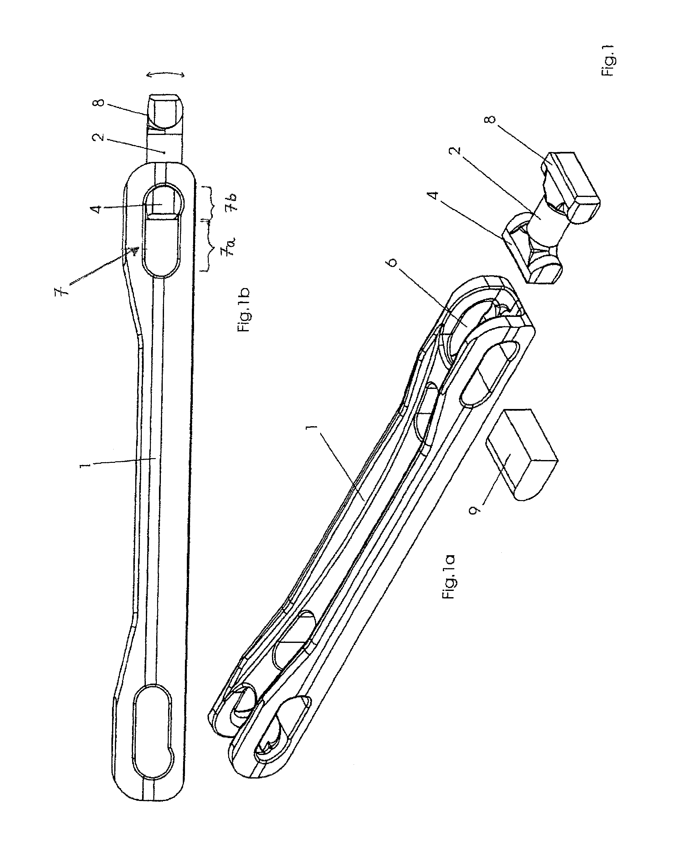
[0034]The plug-in coupling system connects at least two rod segments 1 to a second rod segment 2. For this purpose, a sacrificial element 2 with its stop ridge 4 is inserted, at one end of the rod segment 1, through a coupling mouth 6 into a recess 7. The recess 7 has first and second portions 7a, 7b of different widths. The stop ridge can be slid from the first portion 7a to the second portion 7b. Then, via a second stop ridge 8 of the sacrificial element, a second rod segment (not illustrated) is hinged on. The shape of the stop ridge allows for pivoting the rod segments relative to each other in one plane. By using a fixation block 9 as an elastic damper, the pivoting can be prevented or limited. Accordingly, the fixation block 9 is rigid or elastic.

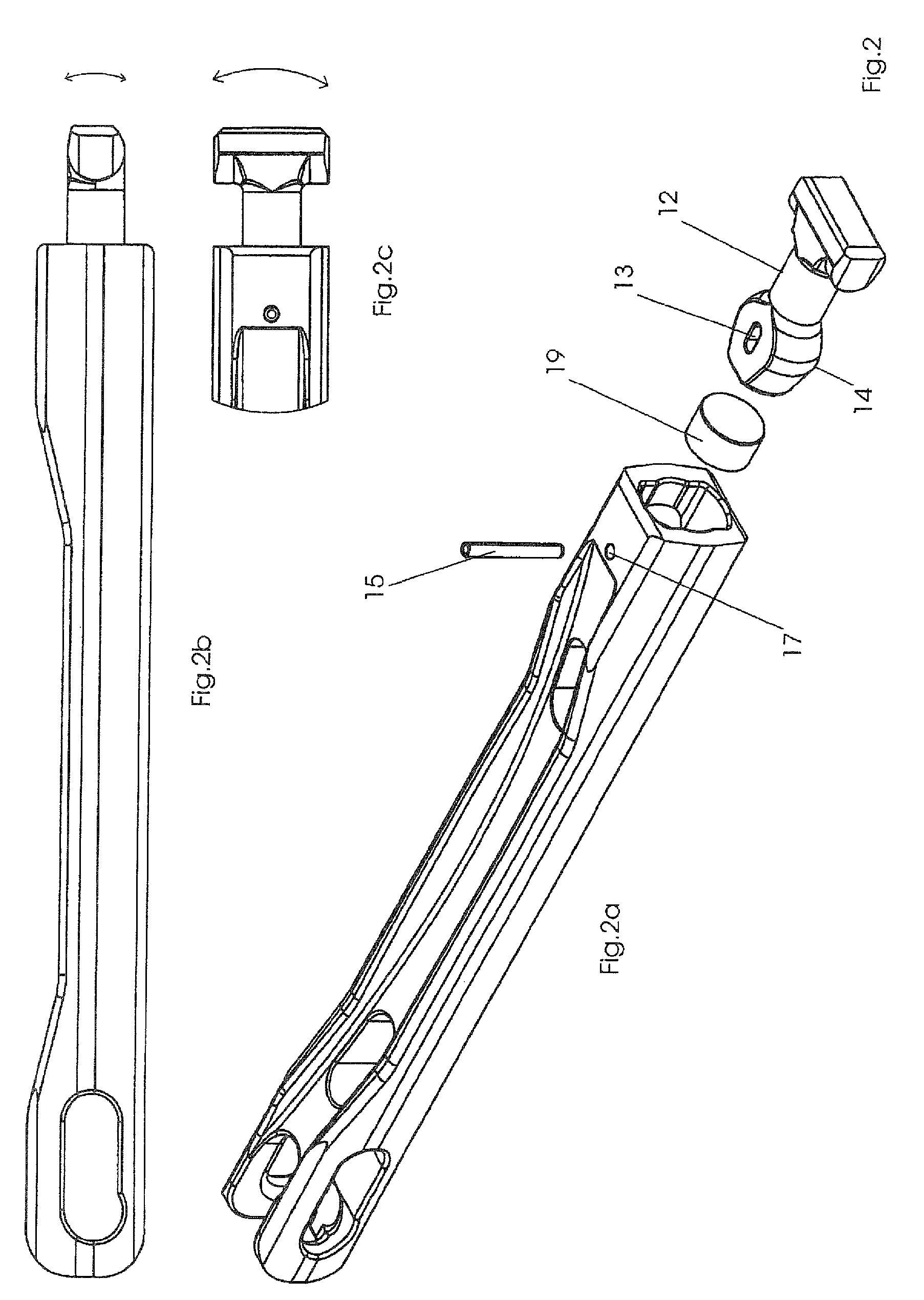
[0035]FIG. 2 shows an alternative embodiment in which the sacrificial element 12 has on one side a connection journal 14 having partly spherical shape. In addition, this embodiment has a longitudinal receptacle 13 for a safety pin 15,...


PUM

PropertyMeasurementUnit
Areaaaaaaaaaaa

Abstract

The invention relates to a coupling system for rod segments for use in horizontal earth boring, wherein the ends of the rod segments are interlinked via a separate sacrificial element which can be used as a predetermined breaking point or which allows the rod segments to be pivoted relative each other.

Description

CROSS-REFERENCES TO RELATED APPLICATIONS[0001]This application is the U.S. National Stage of International Application No. PCT / EP2008 / 002706, filed Apr. 4, 2008, which designated the United States and has been published as International Publication No. WO 2008 / 122416 and which claims the priorities of German Patent Applications, Serial No. 10 2007 016 822.7, filed Apr. 5, 2007, and Serial No. 10 2007 016 824.3, filed Apr. 5, 2007, pursuant to 35 U.S.C. 119(a)-(d).BACKGROUND OF THE INVENTION[0002]The invention relates to a rod coupling as it is used for connecting rod assemblies for underground horizontal boring and trench-less installation or replacing of pipelines (horizontal boring hereinbelow).[0003]In horizontal boring, individual rod assemblies are strung together, connected with each other and moved through the ground by means of a push, pull, or rotary drive. In the case of longer borings, the rod assembly includes multiple rod segments which are, in accordance with the progr...

Claims


Application Information

Patent Timeline
IPC IPC(8): E21B17/02E21B17/046
CPCE21B17/046Y10T29/49718Y10T403/7005F16B2200/63
Inventor PUTTMANN, FRANZ-JOSEF
Owner TRACTO TECHN
Why Eureka
Try Eureka