
Multi cyclone dust-separating apparatus of vacuum cleaner

a vacuum cleaner and dust separation technology, applied in the field of vacuum cleaners, can solve the problems of increased pressure loss, increased flow speed of drawn-in air, deterioration of dust separation efficiency, etc., and achieve the effect of reducing operating noise and reducing pressure loss

Inactive Publication Date: 2008-10-30
SAMSUNG GWANGJU ELECTRONICS CO LTD
View PDF4 Cites 40 Cited by
  • Summary
  • Abstract
  • Description
  • Claims
  • Application Information

AI Technical Summary

Benefits of technology

[0008]An aspect of the present disclosure is to address at least the above problems and / or disadvantages and to provide at least the advantages described below. Accordingly, an aspect of the present disclosure is to provide a multi cyclone dust-separating apparatus having a reduced operating noise and a reduced pressure loss.

Problems solved by technology

As a result, the conventional cyclone dust-separating apparatus presents a problem that a dust-separating efficiency is deteriorated.
However, in the multi cyclone dust-separating apparatus, there is a problem that since a cyclone body of each of the cyclones is formed in a linear cylinder shape, the diameter of which is uniform in a longitudinal direction thereof, or a shape having a truncated cone portion at a lower part thereof, the drawn-in air increases its flowing speed when it is discharged through an air discharging part of the cyclone body after flowing into the cyclone body.
Such an increase in the flowing speed of the air at the air discharging part not only increases a pressure loss, but also increases an operating noise.

Method used


Image

  • Multi cyclone dust-separating apparatus of vacuum cleaner
  • Multi cyclone dust-separating apparatus of vacuum cleaner
  • Multi cyclone dust-separating apparatus of vacuum cleaner

Examples


Embodiment Construction

[0029]Hereinafter, a multi cyclone dust-separating apparatus of a vacuum cleaner according to certain exemplary embodiments of the present disclosure will be described in detail with reference to the accompanying drawing figures.

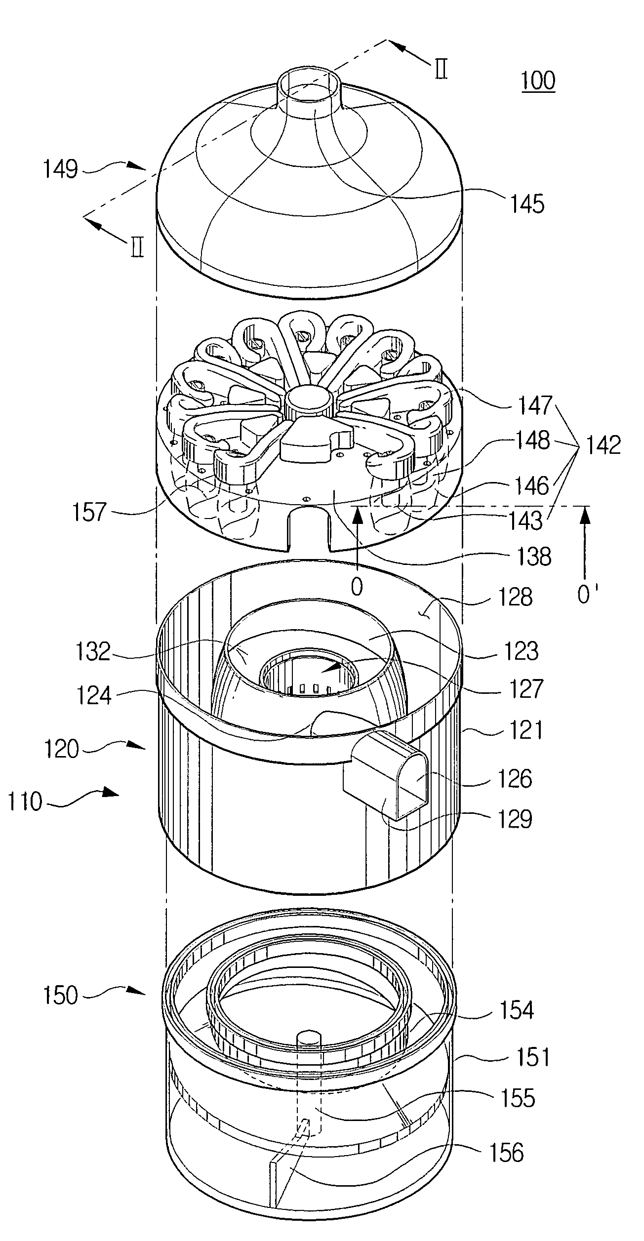
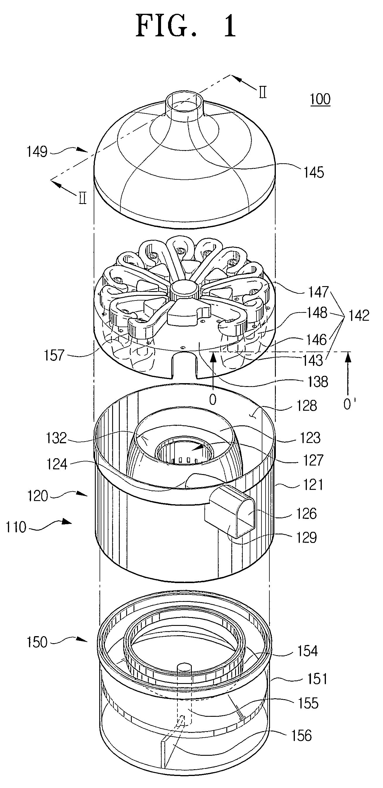
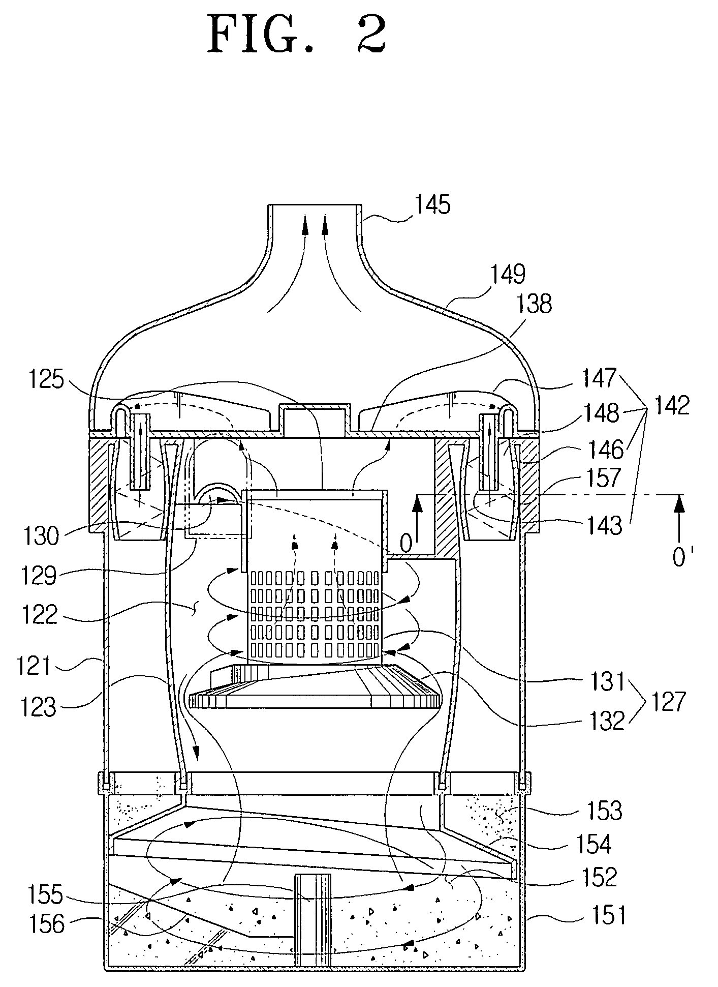
[0030]FIGS. 1 and 2 are an exploded perspective view and a cross-sectional view, respectively, exemplifying a multi cyclone dust-separating apparatus of a vacuum cleaner according to a first exemplary embodiment of the present disclosure.

[0031]Referring to FIGS. 1 and 2, the multi cyclone dust-separating apparatus 100 according to the first exemplary embodiment of the present disclosure includes a cyclone unit 110, a cover member 149 joined to an upper part of the cyclone unit 110 and a dust collecting unit 150 joined to a lower part of the cyclone unit 110.

[0032]The cyclone unit 110 is provided with a first cyclone 120, and a plurality of second cyclones 142. The first cyclone 120 is made up of a housing 121, a first cyclone body 123, an inflow pipe 129, an...


PUM

PropertyMeasurementUnit
Lengthaaaaaaaaaa
Diameteraaaaaaaaaa

Abstract

A multi cyclone dust-separating apparatus is disclosed that includes a cyclone unit having a first cyclone, a plurality of second cyclones, and a dust collecting unit. The first cyclone is disposed so that a longitudinal axis thereof is substantially vertically arranged. The first cyclone separates relatively large dust or dirt from air drawn in through a first air inflow part. Each of the second cyclones is disposed so that longitudinal axes thereof are substantially vertically arranged. Each of the second cyclones has a second air inflow part to communicate with the first cyclone and an air discharging part to discharge the air. The second cyclones separate relatively minute dust or dirt from the air drawn in through the second air inflow part. The dust collecting unit is disposed below the cyclone unit to collect and store the dust or dirt separated from the air by the cyclone unit.

Description

CROSS-REFERENCE TO RELATED APPLICATIONS[0001]This application claims the benefit under 35 U.S.C. § 119(a) of Korean Patent Application No. 10-2007-0039764, filed on Apr. 24, 2007, in the Korean Intellectual Property Office, the entire content of which is hereby incorporated by reference.BACKGROUND OF THE INVENTION[0002]1. Field of the Invention[0003]The present disclosure relates to a vacuum cleaner. More particularly, the present disclosure relates to a multi cyclone dust-separating apparatus of a vacuum cleaner, which draws in an external air and then separates dust or dirt by several stages therefrom.[0004]2. Description of the Related Art[0005]In general, a cyclone dust-separating apparatus provided in a vacuum cleaner is an apparatus, which whirls air laden with dirt or dust and separates the dirt or dust therefrom. Such a cyclone dust-separating apparatus has been recently widely used because it can be semi-permanently used without any inconvenience of frequently replacing dus...

Claims


Application Information

Patent Timeline
IPC IPC(8): B04C5/103B04C5/24
CPCA47L9/1608A47L9/1625A47L9/1641A47L9/165A47L9/1658Y10S56/03B04C5/081B04C5/13B04C5/185B04C5/26B04C5/28A47L9/1683A47L9/16
Inventor OH, JANG-KEUNHAN, JUNG-GYUNKIM, MIN-HA
Owner SAMSUNG GWANGJU ELECTRONICS CO LTD
Learn More