Microscope with dual image sensors for rapid autofocusing

a microscope and image sensor technology, applied in the field of microscopes, can solve the problems of time delay that prevents rapid autofocusing, microscope may exhibit mechanical instability, and single reference point may lack sufficient information for accurate autofocusing

Active Publication Date: 2008-10-30
LEICA MICROSYSTEMS CMS GMBH
View PDF14 Cites 44 Cited by
  • Summary
  • Abstract
  • Description
  • Claims
  • Application Information

AI Technical Summary

Benefits of technology

This patent describes a new type of microscopes called digital optical mice which have two different sensors: one for taking pictures quickly (called the main camera) and another for making sure everything is focused properly (called the focus camera). By analyzing these images, the mouse can automatically find the best way to capture high-quality photos of samples. This technology makes it easier and more efficient to use advanced imaging techniques in biological research.

Problems solved by technology

The patent text discusses the need for a digital optical microscope that can quickly and accurately focus on a sample. This is challenging because the sample, microscope, and other factors can cause the sample to move or become misaligned, making it difficult to keep it in focus. Conventional microscopes use either a single reference point or multiple images to determine the optimal focal distance, but these methods have limitations in terms of accuracy and speed. Therefore, there is a need for a microscope that can perform accurate and rapid autofocusing.

Method used


Image

  • Microscope with dual image sensors for rapid autofocusing
  • Microscope with dual image sensors for rapid autofocusing
  • Microscope with dual image sensors for rapid autofocusing

Examples


Embodiment Construction

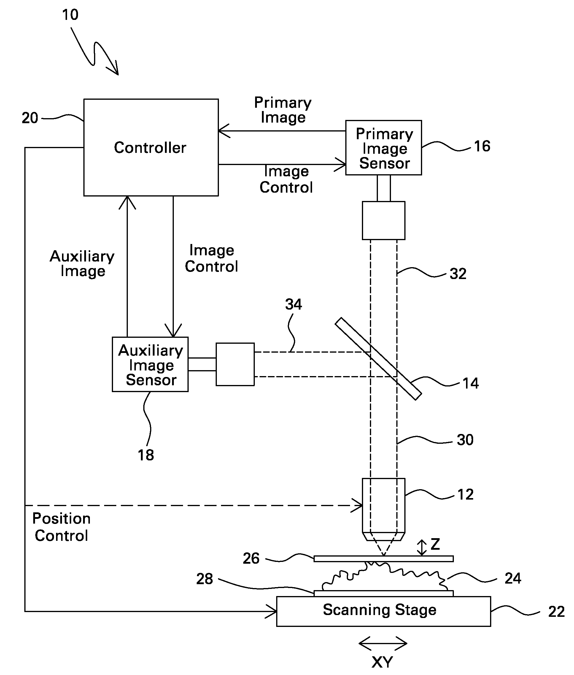
[0017]FIG. 1 illustrates one embodiment of a digital optical microscope 10 that includes objective lens 12, beam splitter 14, primary image sensor 16, auxiliary image sensor 18, controller 20 and scanning stage 22.

[0018]Sample 24 is disposed between coverslip 26 and slide 28, and sample 24, coverslip 26 and slide 28 are supported by scanning stage 22. Coverslip 26 and slide 28 may be transparent glass, while sample 24 may represent a wide variety of objects or samples including biological samples. For example, sample 24 may represent biopsy tissue such as liver or kidney cells. In a non-limiting example, such biopsy tissue samples may have a thickness that averages 5 microns and varies by several microns and may have a lateral surface area of approximately 15×15 millimeters, and.

[0019]Objective lens 12 is spaced from sample 24 by a focal distance that extends along an optical axis in the Z (vertical) direction, and objective lens 12 has a focal plane in the XY (lateral) directions. ...


PUM


Abstract

A digital optical microscope includes a primary image sensor that generates a primary image of a sample at a primary frame rate, an auxiliary image sensor that generates an auxiliary image of the sample at an auxiliary frame rate that is faster than the primary frame rate, and a controller that adjusts a focal distance between an objective lens and the sample along an optical axis in response to the auxiliary image, thereby autofocusing the primary image on the sample. The primary image sensor generates the primary image in response to the autofocusing.

Description


Claims


Application Information

Patent Timeline
Owner LEICA MICROSYSTEMS CMS GMBH
Why Eureka
Try Eureka