Lancet Cartridges and Lancing Devices

a technology which is applied in the field of lancing device and cartridge, can solve the problems of increasing the part count of the lancing device, increasing the risk of unintentional lancing, and elderly patients, and achieving the effect of low part count, low chance of defects and malfunctions

Active Publication Date: 2008-05-08
AGAMATRIX INC
View PDF17 Cites 111 Cited by
  • Summary
  • Abstract
  • Description
  • Claims
  • Application Information

AI Technical Summary

Benefits of technology

[0011]In accordance with the current invention, lancet cartridges are provided that have a low part count and a low opportunity for defects and malfunctions. The lancet cartridges of the present invention are suitable used in connection with lancing devices and may be embodied in single-lancet cartridges or in multiple lancets housed within a single cartridge. Further, the lancet cartridges of the invention may retract lancets back into a protective casing after each use.

Problems solved by technology

More complex lancing devices may even contain motor driven lancets that are extended and retracted by a computer driven process.
Many of these patients are elderly and may not have the coordination and dexterity required to manipulate a complex lancet device.
Unfortunately, this process often includes removing the unprotected lancet while running the risk of unintentional lancing.
However, these improvements share the major drawback of increasing the part count of a lancing device.
Increasing the part count, in turn, increases manufacturing costs, increases the opportunity for defects and malfunctions, and decreases the ease of use of the device.

Method used


Image

  • Lancet Cartridges and Lancing Devices
  • Lancet Cartridges and Lancing Devices
  • Lancet Cartridges and Lancing Devices

Examples


Embodiment Construction

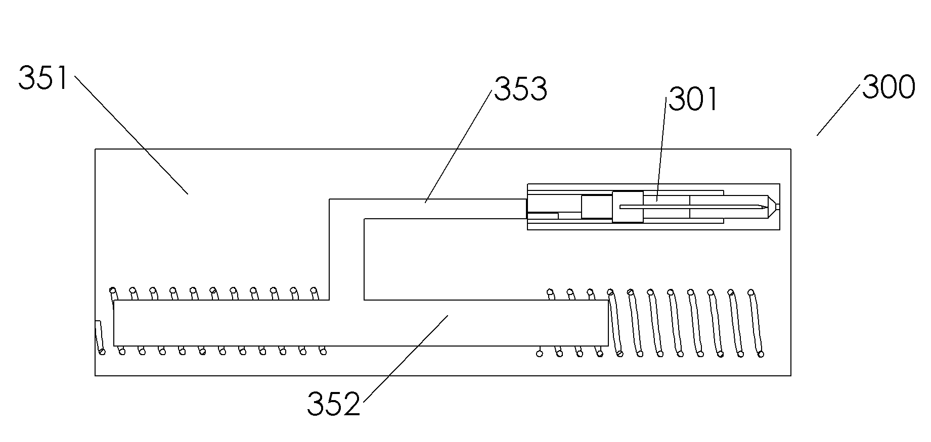
[0051]The present invention provides lancet cartridges and improved lancing devices comprising these lancet cartridges. The lancet cartridges and lancing devices of the present invention are user-friendly and easy to use and have low part counts and low opportunity for defects and malfunctions.

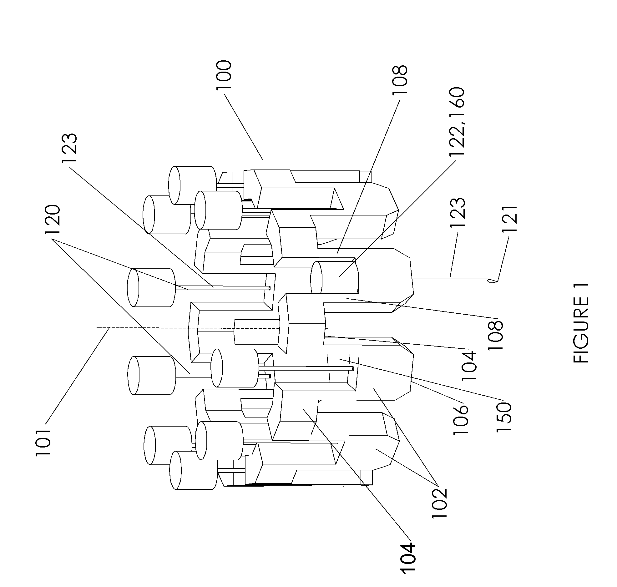
[0052]Although there are several different methods and apparatuses which may used to practice this invention, the embodiments of the invention share the common element of a U-shaped support having a pair of deformable leg portions and an associated lancet where a portion of the lancet is disposed between the pair of deformable leg portions of the U-shaped support. The deformable leg portions change shape from an initial shape to an extended shape in response to an external applied force that is generally applied via an associated lancing device. The deformable leg portions of the U-shaped support assume a retracted shape which is substantially the same as the initial shape once the force is re...


PUM


Abstract

A lancet cartridge has a U-shaped support with a pair of anchor portions, a base portion, and a pair of deformable leg portions connecting the anchor portions to the base portion. The pair of deformable leg portions change shape from an initial shape to an extended shape in response to an external applied force and recover to a retracted shape upon removal of the force. The lancet cartridge also has a lancet having a tip end, an opposing base end, and an axis extending between the tip end and the base end. A portion of the lancet is disposed between the pair of deformable leg portions of the U-shaped support. The lancet is movable between a starting position, an extended puncturing position, and an ending position along the axis of the lancet in a path defined by the U-shaped support. When the lancet is in the starting position, the tip end of the lancet is disposed at least partially through the base portion of the U-shaped support, and the U-shaped support is in the initial shape. When the lancet is in the extended puncturing position, the tip end of the lancet is extended through the base of the U-shaped support, and the U-shaped support is in the extended shape. When the U-shaped support recovers to its retracted shape upon removal of the force, the lancet is retracted to the end position.

Description

BACKGROUND OF THE INVENTION[0001]This application relates to a lancet cartridge suitable for use with a lancing device by a diabetic, or other user, to obtain small samples of blood, interstitial fluid, or tissue from the fingers, forearm, or other body portions. The invention also relates to an improved lancing device comprising the lancet cartridges of the present invention.[0002]Lancing devices are well known. Most include an outer casing, a lancet (e.g. a needle or a blade), a priming mechanism to produce and store potential energy (usually in a coil spring), and a trigger to release the stored energy to produce a lancing motion of the lancet with a hammer. Some also include a cap to cover the lancet needle in order to preserve sterility prior to use as well as helping avoid unintended skin piercing with the lancet prior to and after use. More complex lancing devices may even contain motor driven lancets that are extended and retracted by a computer driven process. Lancing devic...

Claims


Application Information

Patent Timeline
Patent Type & Authority Applications(United States)
IPC IPC(8): A61B17/32
CPCA61B5/15146A61B5/1411A61B5/150022A61B5/150412A61B5/150503A61B5/150572A61B5/15113A61B5/15117A61B5/1513A61B5/15151A61B5/15161A61B5/15163
Inventor BERKOVITCH, FREDERICKBOOZER, BRADFLAHERTY, JOSEPHGOLNIK, TIMOTHYIYENGAR, SRIDHARKILPINEN, MALIAVU, SONNY
Owner AGAMATRIX INC
Why Eureka
Try Eureka