Wave power generator systems

a generator and wave technology, applied in water-power plants, machines/engines, mechanical equipment, etc., can solve problems such as dripping waves, and achieve the effect of dripping waves, shortening and lengthening anchor lines

Active Publication Date: 2008-10-30
SINGLE BUOY MOORINGS INC
View PDF24 Cites 51 Cited by
  • Summary
  • Abstract
  • Description
  • Claims
  • Application Information

AI Technical Summary

Benefits of technology

[0006]When the SSM material withdraws energy from the waves, it also damps the waves. Such dampening of waves can be useful to protect offshore structures.
[0007]The buoy is anchored so the anchor line is always under tension. A system can be provided that shortens and lengthens the anchor line(s), especiall

Problems solved by technology

When the SSM material withdraws energy

Method used


Image

  • Wave power generator systems
  • Wave power generator systems
  • Wave power generator systems

Examples


Embodiment Construction

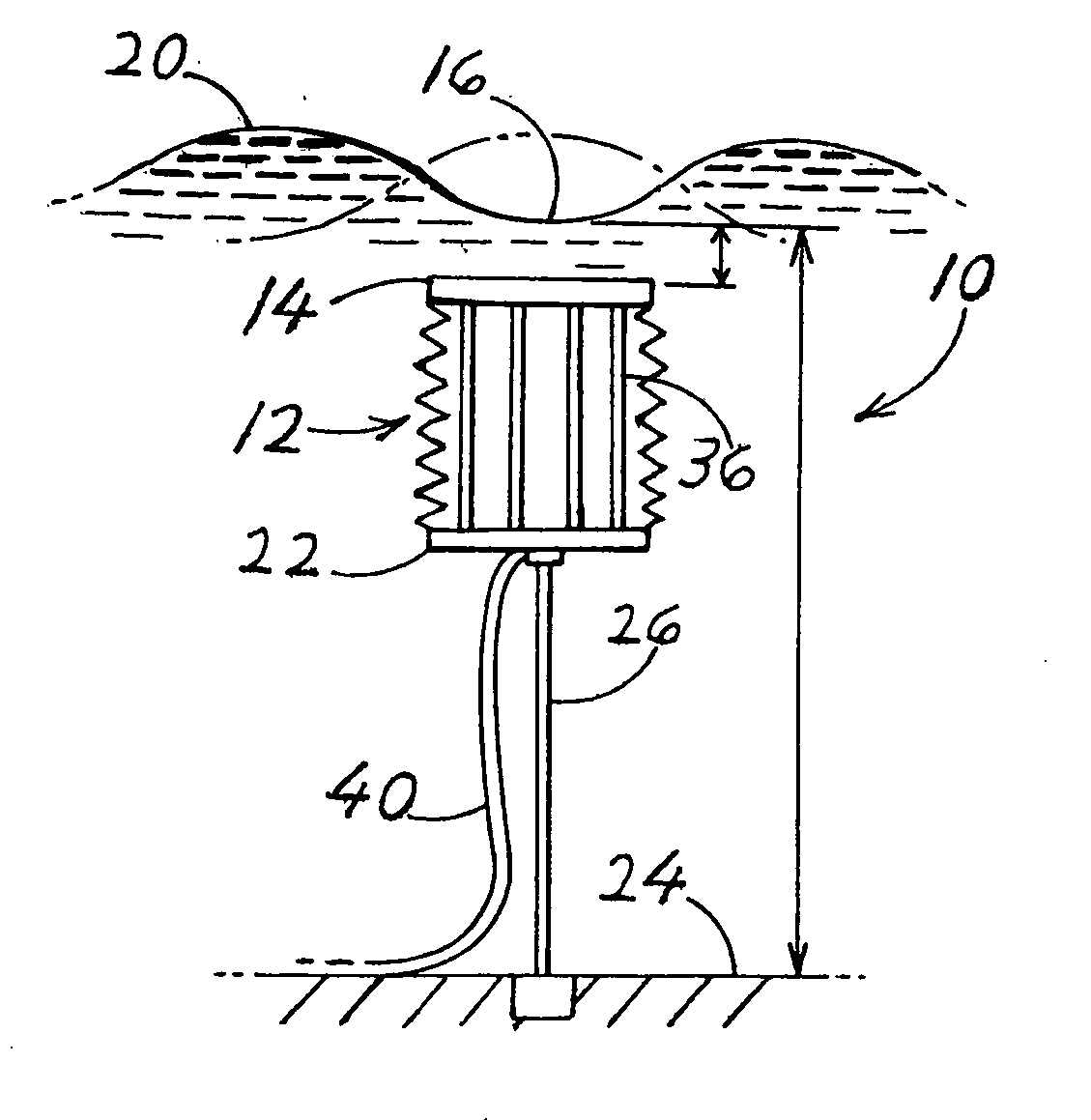
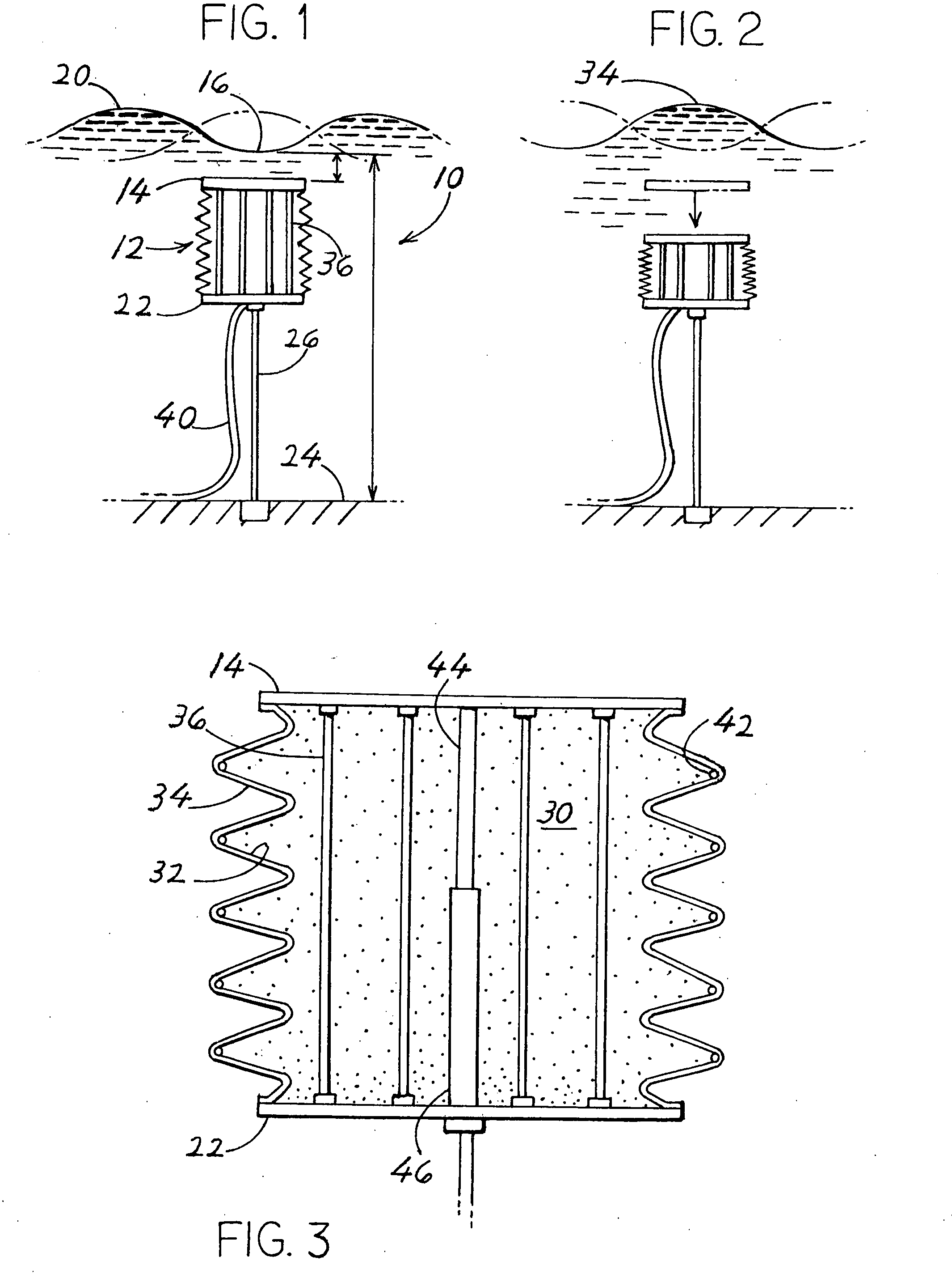
[0022]FIG. 1 shows a wave power generating system, or generator, 10 which includes a buoyant element 12 in the form of a buoy that lies in the sea, and that has an upper part 14 that lies closely under the troughs 16 of sea waves 20. The element 10 has a lower part 22 that is anchored to the sea floor 24 by an ordinary (e.g. steel cable) tether line, or anchor line 26. The buoy 12 has a construction such as shown in FIG. 3, with slightly pressured air 30 lying in a chamber 32 formed between the upper and lower parts 14, 22 and within a bellows side wall 34. When the trough 16 of a wave moves to a position over the buoy, the water pressure in the sea closely below the trough decreases. The buoy upper part 14 then moves up to the position of FIG. 1 under the upward spring bias of pressured air in the chamber. When the crest 34 (FIG. 2) of a wave moves to a position over the buoy, the water pressure in the sea closely below the crest increases while water moves into the region above an...


PUM


Abstract

Systems are provided for obtaining electrical energy from sea waves using deflectable material, especially EAP (electro-active polymers) type SSM (stretchable synthetic material) that generates electricity when an electrostatic charge is applied to the polymer and it is stretched. In one system (10), a buoyant element (12) has upper and lower parts (14, 22) connected by a quantity (36) of SSM, with the lower part anchored at a fixed height above the sea floor (24) and with the upper part movable vertically to stretch and relax the SSM as waves pass over. In another system (50) the buoy is rigid, but is anchored to the sea floor by at least one line (60) that includes, or is connected to at least a length (64) of SSM material. In still another system (160) a plurality of rigid buoys (162) that float on the sea surface, are connected in tandem by SMM (166, 172) that is stretched and relaxed as the buoys pivot relative to each other in following the waves. The buoys preferably lie with at least 80% of their volume below the average sea surface.

Description

CROSS-REFERENCE[0001]Applicant claims priority from U.S. provisional patent applications 60 / 926,177 filed Apr. 25, 2007 and 60 / 994,773 filed Sep. 21, 2007.BACKGROUND OF THE INVENTION[0002]Wave energy is concentrated at the sea surface, such as within 25 meters of the surface. Wave energy decreases with depth below the surface. Near the surface, there is vigorous movement of water up and down and horizontally, and the pressure of water repeatedly increases as a wave crest moves over a location and repeatedly decreases as the trough of a wave moves over the location. Several systems have been proposed for converting wave energy into electricity, as in U.S. Pat. No. 6,229,225 by Carroll, where a mooring line that holds a buoy operates a deep underwater hydraulic pump and electrical generator. Any electricity-generating device that lies under water should be as simple as possible.[0003]There have been recent developments of SSM (synthetic stretchable material) such as EPA (electro activ...

Claims


Application Information

Patent Timeline
IPC IPC(8): E02B9/08
CPCE02B9/08Y02E10/38F05B2240/97F03B13/188F03B13/148Y02E10/30
Inventor JEAN, PHILIPPE F.ARDOISE, GUILLAUME A.POLLACK, JACK
Owner SINGLE BUOY MOORINGS INC
Why Eureka
Try Eureka