
Apparatus and method for flexible spinal fixation

a technology of flexible fixation and apparatus, applied in the field of apparatus and method for flexible fixation of vertebral columns, can solve the problems of significant patient disability, loss of support by this instrumentation, and inordinate stress and degeneration of remaining segments, and achieve the effect of low stretch and high tensile strength

Inactive Publication Date: 2008-10-30
HOLT DEV
View PDF27 Cites 102 Cited by
  • Summary
  • Abstract
  • Description
  • Claims
  • Application Information

AI Technical Summary

Benefits of technology

This patent describes a new type of connector for rods made from flexible materials that can be used in various medical applications. It consists of a main rod with an added layer of strong but elastic reinforcement running throughout its length. This allows it to bend and move without breaking easily. Different types of reinforcements can be used including cables, fabrics, and other materials like KEVLAR® or stainless steel. By adjusting how tightly the reinforcement is attached to the rod, different levels of flexibility can be achieved. Overall, this design makes it easier to create durable connectors between two parts while still allowing them to move around naturally.

Problems solved by technology

The technical problem addressed in this patent is finding a better way to stabilize vertebral columns without causing damage to surrounding structures and promoting excessive stress on the body's own natural repair mechanisms. Current methods require expensive and invasive surgery, produce pain and discomfort, and may even cause complications. There is also a need for a more efficient and effective means of providing stability while allowing some flexibility in the spine.

Method used

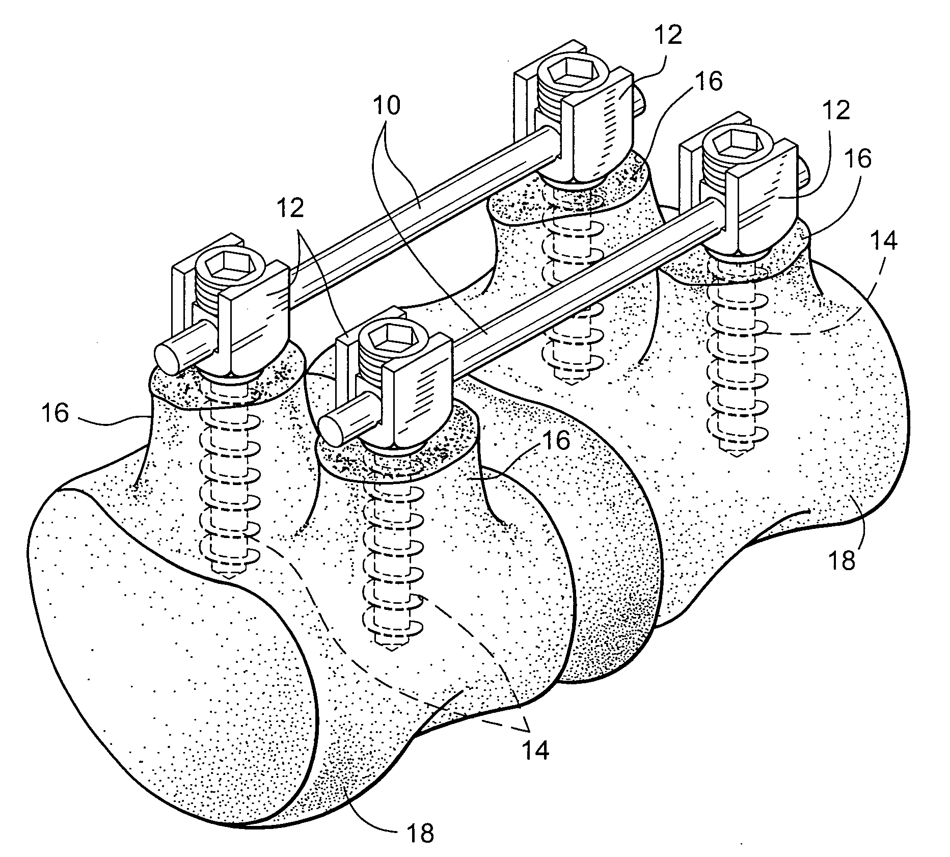
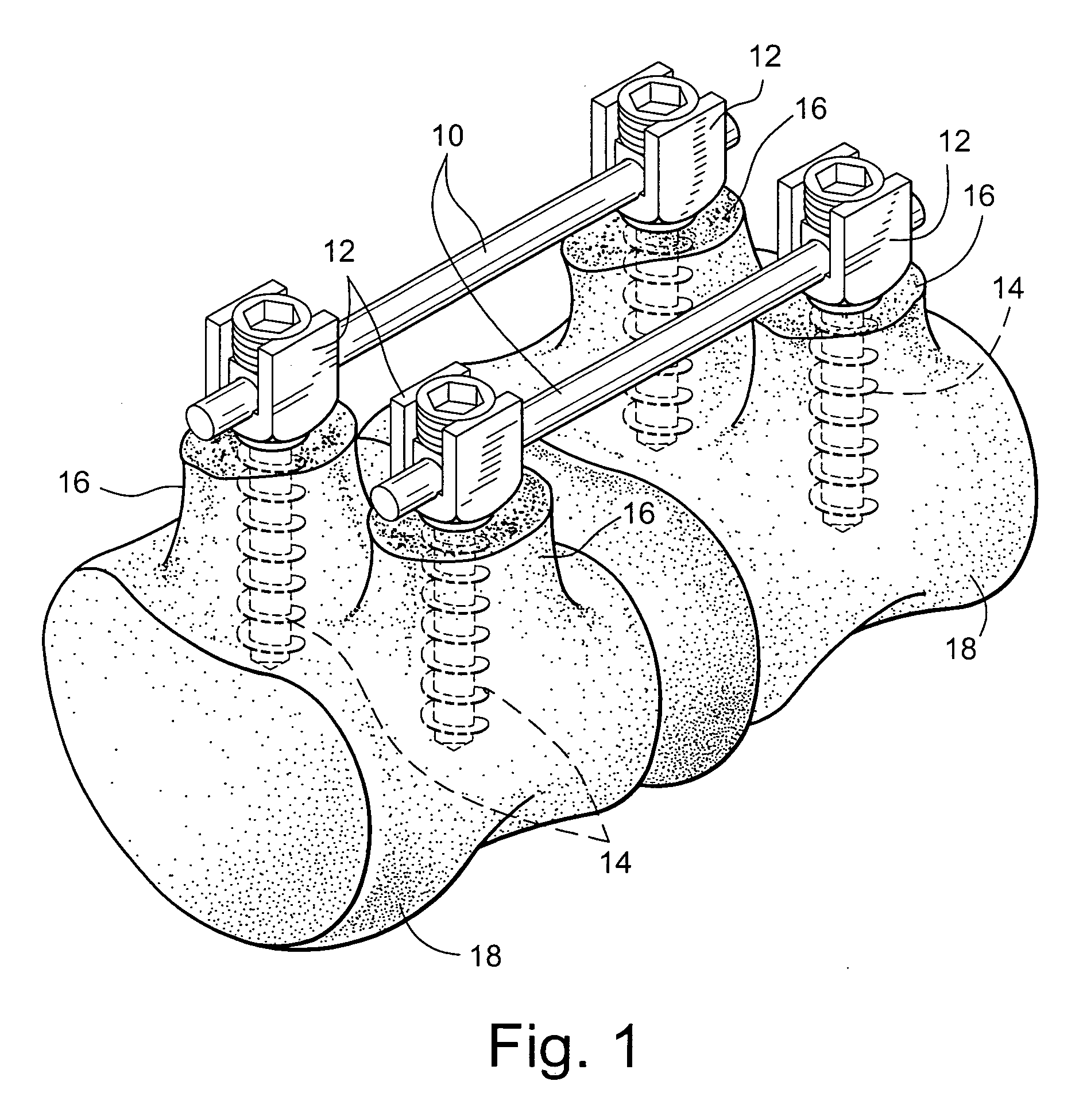
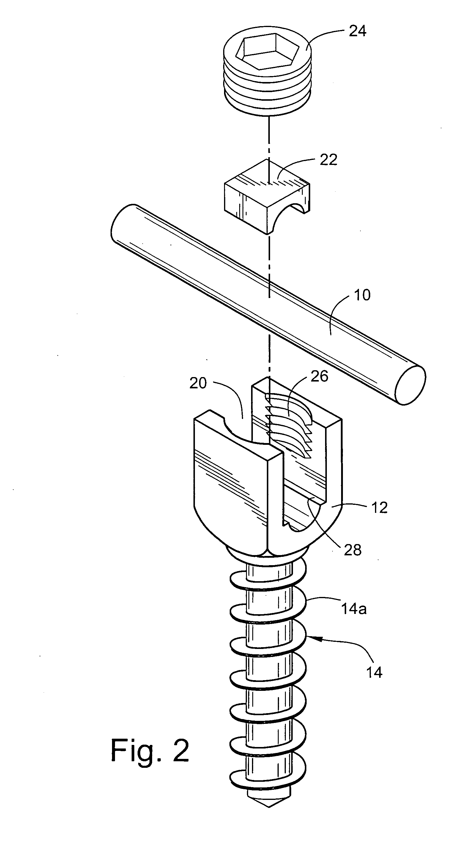

Image

  • Apparatus and method for flexible spinal fixation
  • Apparatus and method for flexible spinal fixation
  • Apparatus and method for flexible spinal fixation

Examples


second embodiment

[0031]FIG. 7 illustrates the flexible composite connecting rod 10′ (or 110 or 210) wherein a single large flexible reinforcing element 10c extends longitudinally through the entire length of the rod member 10d and is slidable within an aperture therein or is bonded thereto in any suitable manner. In this embodiment, the rod member 10d and flexible reinforcing element 10c may be formed of any construction or suitable materials as hereinbefore described.

third embodiment

[0032]FIG. 8 discloses the flexible composite connecting rod 10″ (or 110 or 210) which comprises a rod member 10e and a tubular flexible reinforcing element 10f extending through the entire length thereof and slidably mounted within or connected thereto in any suitable manner. Within the scope of the present invention, the tubular element 10f may be disposed within a central elongated opening in the rod member 10e, or may be embedded in the central portion of a solid rod member. The rod member 10e and tubular reinforcing element 10f may be of any suitable construction or materials as hereinbefore described.

[0033]FIGS. 11a and 11b disclose fourth and fifth embodiments of the flexible composite connecting rod 10′″, 10″″ (or 110 or 210) which comprises a rod member 10g (FIG. 11a), 10h (FIG. 11b) and a tubular flexible reinforcing element 10i extending through the entire length thereof and slidably mounted within or connected thereto in any suitable manner. Within the scope of the prese...


PUM


Abstract

Apparatus for connecting and stabilizing adjacent vertebral segments, comprising a flexible composite connecting rod extending between the segments, and connection devices for connecting the rod to the vertebral segments. The rod comprises a rod member formed of a flexible plastic material having a predetermined compression strength, and a high tensile strength, low stretch, flexible reinforcing element extending longitudinally through the entire length of the rod member. The reinforcing element may be in the form of a single cord, rope, braid or monofilament, a plurality of substantially parallel cords, ropes, braids or monofilaments, or a tubular cord, rope, braid or woven or wire mesh strain relief device extending through the rod member in slidable relation or bonded thereto.

Description


Claims


Application Information

Patent Timeline
Owner HOLT DEV
Learn More