
Building Finite State Machine Model

a state machine and model technology, applied in the field of building finite state machine models, can solve the problems of time-consuming, laborious and time-consuming, manual checking of the completeness of the state machine based on state transition tables, and the editor of the visual state machine, so as to reduce the learning curve for designers. , the effect of fast development of state machines

Inactive Publication Date: 2008-10-30
SUOMEN 3C
View PDF7 Cites 19 Cited by
  • Summary
  • Abstract
  • Description
  • Claims
  • Application Information

AI Technical Summary

Benefits of technology

[0009]The solution according to the invention provides several advantages. The solution enables fast development of state machines in a graphical modelling environment. In an embodiment of the invention, state transition tables are automatically created, maintained, and seamlessly and dynamically integrated to the tool that is used for creating state machine models. The state transition table may be automatically generated based on the meta-information available about possible events for each state. This enables predictive building of state machines and automatic checking and verification of completeness. When designing a state machine model, the tool is configured to find out available triggering events and propose transitions and destination states to be added to the state machine model on the basis of the events. Automatic checking may be performed for inclusion of defined states and transitions. Thus, the designer does not need to manually draw and lay out the state machine diagrams. Also, the proposed method helps the designer to find out all the possible transitions, and thus aids to reach the completeness of the state machine diagram.
[0010]Furthermore, the invention lowers the learning curve for designers when they start developing state machines based designs for unfamiliar target software environments.

Problems solved by technology

There are several problems related to current visual state machine editors.
Editing, changing and maintaining the diagram is laborious and time-consuming.
The manual creation and maintaining of state transition tables and manual checking of the completeness of the state machine based on state transition tables is error-prone and time-consuming.

Method used


Image

  • Building Finite State Machine Model
  • Building Finite State Machine Model
  • Building Finite State Machine Model

Examples


Embodiment Construction

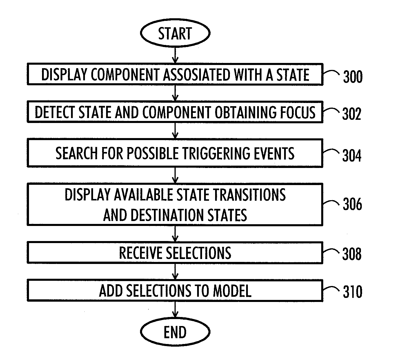
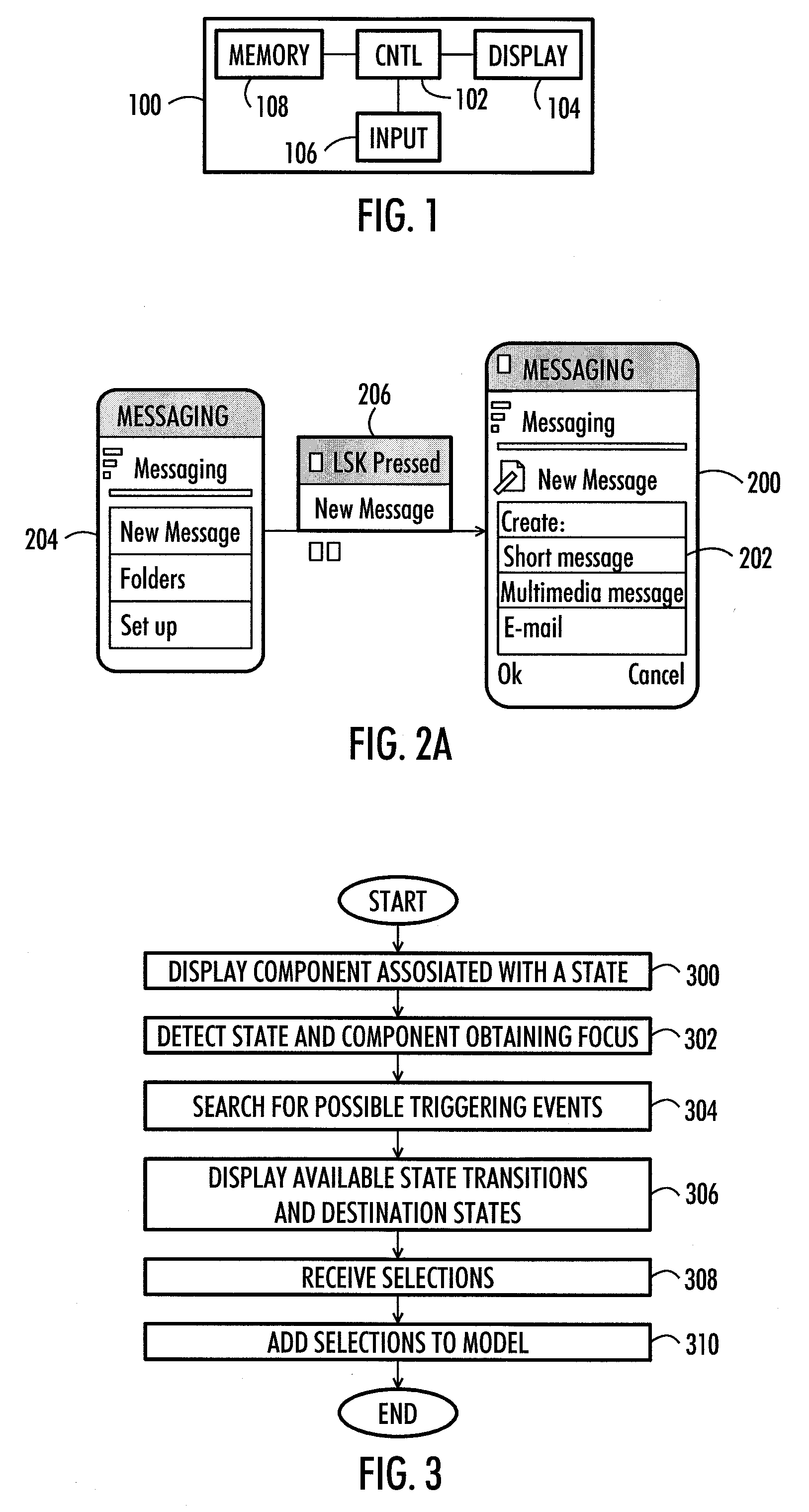
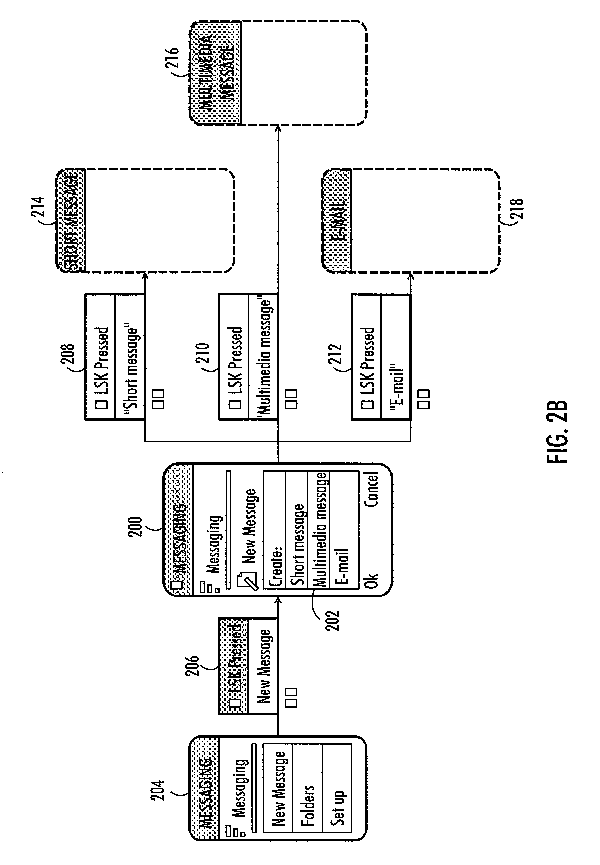
[0016]In general, a state machine is a model that stores the status of a modelled item at a given time and can operate on input to change the status and / or cause an action or output to take place for any given change. State machine models are used to develop and describe device or software application interactions and behaviour. Properties describing a state machine can be listed as follows. A state machine has an initial state. The state machine receives a set of possible input events. Thus, a state machine cannot receive unknown input. The state machine comprises a set of new states that may result from the input. The state machine further comprises a set of possible actions or output events that result from a new state. When an input event causes the state machine to move from a state to another state, a state transition occurs. It is possible to define a state transition function that maps states and inputs to states.

[0017]A state machine that has a limited number of possible st...


PUM


Abstract

A solution for building a finite state machine model is provided. The solution comprises: displaying (300) on a display a state associated with at least one modelling component, the component comprising information about available triggering events, detecting (302) the state and a modelling component obtaining focus, searching (304) for possible outgoing state transitions and destination states related to the state with which the at least one modelling component is associated, displaying (306) the detected outgoing state transitions and destination states, receiving (308) selections of the state transitions and destination states, and adding (310) the selections to the model describing the finite state machine model.

Description

FIELD[0001]The invention relates to building of a finite state machine model. Especially, the invention relates to finite state machines utilising modelling components comprising information about available triggering events.BACKGROUND[0002]In designing technical systems, devices and software applications, it is essential that the operation and behaviour of the system can be specified and verified efficiently. A common approach is to build a model describing the operation of the system. When the behaviour of the system is state-dependent and / or event-driven, a finite state machine may be used to model the system.[0003]For example, in developing software, a model of the software may be developed before the actual software is implemented. A model of a software application may be compared to a blueprint of a physical device. A model utilising a finite state machine may be used in designing, specifying, testing and verifying the operation and dynamic behaviour of software. A known appro...

Claims


Application Information

Patent Timeline
Patent Type & Authority Applications(United States)
IPC IPC(8): G06F17/50G06FG06F30/00
CPCG06F8/10G06F8/38G06F9/444G06F9/4498
Inventor SALMELA, MARKO
Owner SUOMEN 3C
Features
  • Generate Ideas
  • Intellectual Property
  • Life Sciences
  • Materials
  • Tech Scout
  • Unparalleled Data Quality
  • Higher Quality Content
  • 60% Fewer Hallucinations
Learn More