
Signaling light with motion-sensing light control circuit

a control circuit and motion-sensing technology, applied in the direction of instruments, lighting and heating apparatus, semiconductor devices of light sources, etc., can solve the problems of confusion and misdirection, inability to effectively convey the direction of swinging motion, and inability to see or understand the signaled directional flow

Inactive Publication Date: 2008-11-06
SHUSTER GARY S
View PDF48 Cites 96 Cited by
  • Summary
  • Abstract
  • Description
  • Claims
  • Application Information

AI Technical Summary

Benefits of technology

"The present invention is a portable light that dims or shuts off based on the direction of motion. The light can be controlled using a motion sensor and controller that dims or shuts off the light when the light is swung in a different direction. The light can also be used as a flashlight or light wand, and can be manually controlled for intensity. The portable light may also include additional elements such as an infrared beam or laser for use in military applications. The light can be adjusted for different light patterns and focal lengths, and may include more than one lamp controlled by the motion-sensing and control circuit. The technical effects of this invention include improved control and flexibility for a portable light, making it more versatile and user-friendly."

Problems solved by technology

When a light is being moved back-and-forth to direct traffic flow, the people being directed see the light moving back and forth, and cannot see or understand the signaled directional flow.
This may lead to confusion and misdirection.
However, the swinging motion cannot effectively convey a direction of motion.
Various flashlight or handheld signaling devices are known for directional signaling, but none are able to exploit a swinging motion to provide a directional signal.
Directional signaling lights are known that use lighted arrows or moving light arrays, but such lights are not well-suited for portable use, nor do they make use of a natural swinging motion.

Method used


Image

  • Signaling light with motion-sensing light control circuit
  • Signaling light with motion-sensing light control circuit
  • Signaling light with motion-sensing light control circuit

Examples


Embodiment Construction

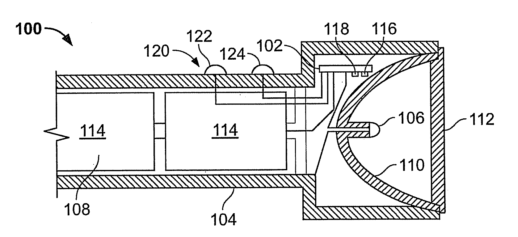
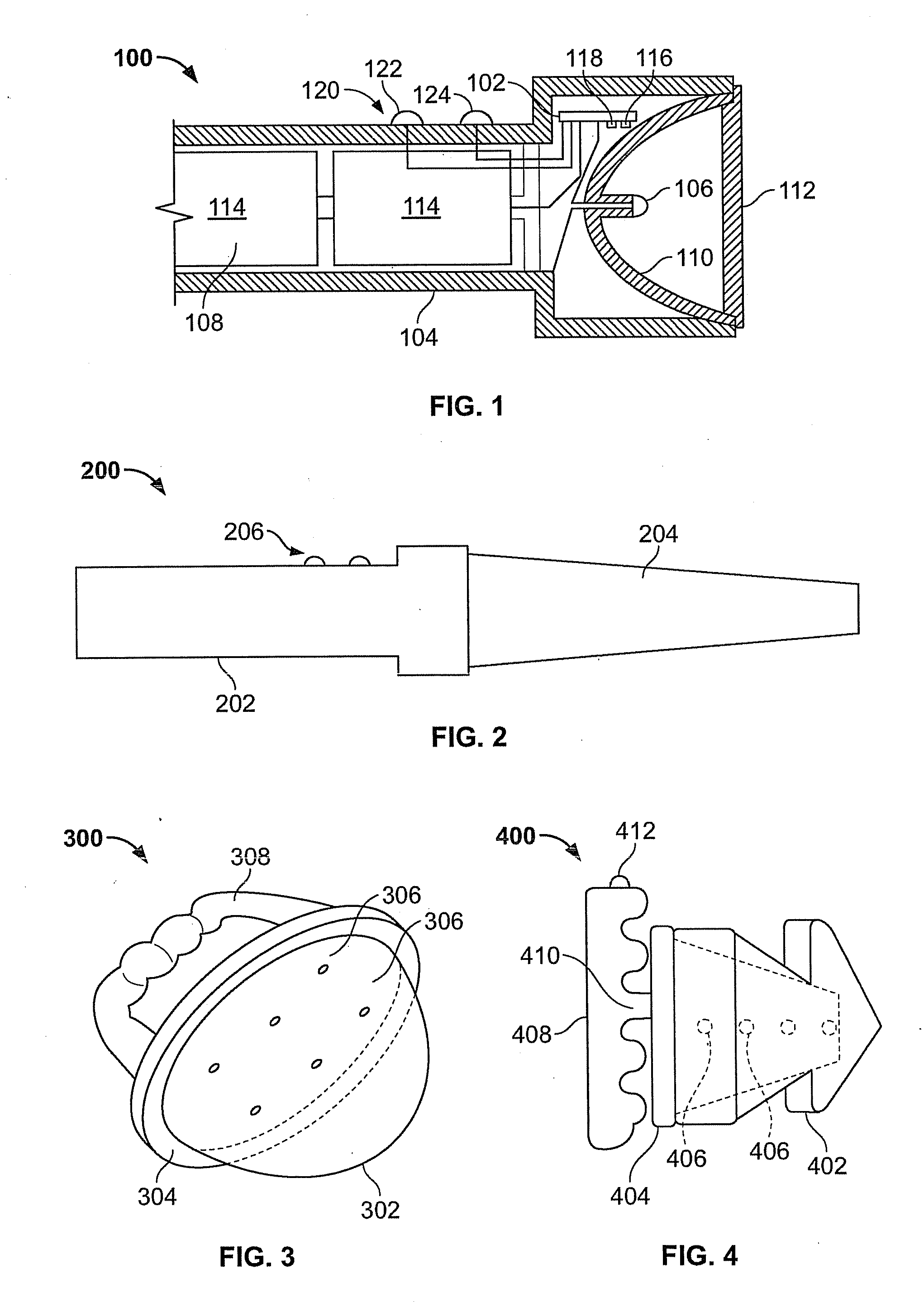
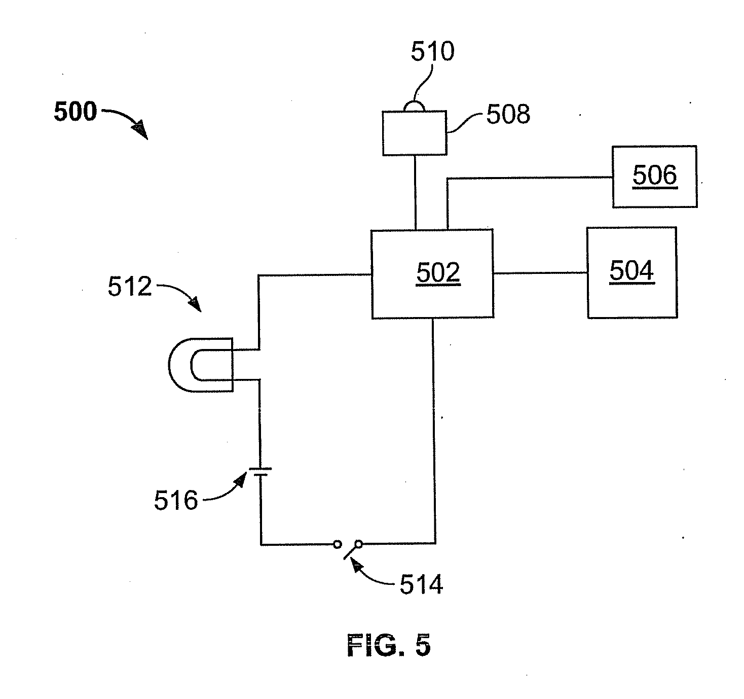
[0022]FIG. 1 shows an exemplary portable light 100 with a motion-sensing fight control circuit 102 coupled to a portable housing 104. Light 100 is configured as a flashlight, but may equally well be configured as a lantern, light wand, or other configuration suitable for grasping with one hand. Portable light 100 may include a housing 104 containing a light element 106 and a portable power source 108. The housing 104 may comprise a plastic material, a glass or carbon fiber composite material, a metal material, or any suitable combination of these or other suitable materials. It may be configured for grasping by hand, or may include a separate handle. The lighting element 106 may comprise an LED lamp, incandescent lamp, infrared lamp, fluorescent lamp, halogen lamp, or laser. A reflector 110 may be used to reflect light in one or more desired directions, to focus light into a beam, or both. The portable light 100 may further compose a transparent or translucent cover 112. The cover 1...


PUM


Abstract

A signaling light, such as a wand light or flashlight, includes a motion sensor coupled to a controller for lamp intensity. When the light is moved in a first direction, the lamp is powered at a baseline intensity. When the light is moved in a second direction generally opposite the first direction, the lamp is switched off or dimmed. When swung in a back-and-forth motion, the light as controlled by the controller thereby appears to move in only one direction, thereby providing a signal indicating a direction of motion.

Description

BACKGROUND[0001]1. Field[0002]The present disclosure relates to portable lights or wands such as are used in signaling traffic or other applications.[0003]2. Description of Related Art[0004]A major use of flashlight signaling devices is for directing traffic, such as automobile and pedestrian traffic. Often, persons directing traffic need a handheld light that can be used to signal pedestrians, passenger vehicles, and commercial vehicles to move in a desired direction. Current hand signaling lights are designed to emit light at a constant intensity regardless of how the light is being moved. When a light is being moved back-and-forth to direct traffic flow, the people being directed see the light moving back and forth, and cannot see or understand the signaled directional flow. This may lead to confusion and misdirection.[0005]At the same time, swinging a light back-and-forth or from side-to-side is a highly effective signaling technique, because the swinging motion makes the swingi...

Claims


Application Information

Patent Timeline
Patent Type & Authority Applications(United States)
IPC IPC(8): G08B5/36
CPCF21L4/027F21V23/0414F21Y2101/02F21V23/0492F21Y2115/10
Inventor SHUSTER, GARY S.
Owner SHUSTER GARY S
Learn More