Wearable human motion applicator

a technology of motion applicators and wearable parts, which is applied in the field of wearable human motion applicators, can solve the problems of insufficient prior art motion applicators, and achieve the effects of quick and sufficient displacement, and quick and sufficient deformation

Inactive Publication Date: 2006-06-06
MATSUSHITA ELECTRIC WORKS LTD
View PDF8 Cites 106 Cited by
  • Summary
  • Abstract
  • Description
  • Claims
  • Application Information

AI Technical Summary

Benefits of technology

[0003]The above insufficiency has been reduced in the present invention which provides an improved human motion applicator which assures a quick and sufficient amount of displacement given to a part of a human body. The human motion applicator in accordance with the present invention includes a support adapted to be fitted on the part of the human body. The support carries at least one electro-active elastic actuator in a force-transmitting relation to the part of the human body. The elastic actuator includes a dielectric core and a pair of electrodes on opposite of the core for receiving a driving DC voltage thereacross. The elastic actuator has a length and elastically deforms in the lengthwise direction to exert a stretching force to the human part to a greater extent as the driving DC voltage increases. The applicator also includes a DC voltage source for providing the driving DC voltage and a controller which applies the driving DC voltage of varying levels to the elastic actuator, thereby generating a varying motion-inducing force to be applied to the human part. Accordingly, the elastic actuator can give quick and sufficient amount of deformation to the part of the human body, giving consistent and smooth motion sufficient for assisting or inducing the motion as intended by the human.

Problems solved by technology

However, due to a limitation to the amount of the displacement and a response speed given to the memory shape alloy, the prior art motion applicator is found insufficient in that it is not completely in match with an actual need of assisting or inducing the human motion.

Method used


Image

  • Wearable human motion applicator
  • Wearable human motion applicator
  • Wearable human motion applicator

Examples


first embodiment

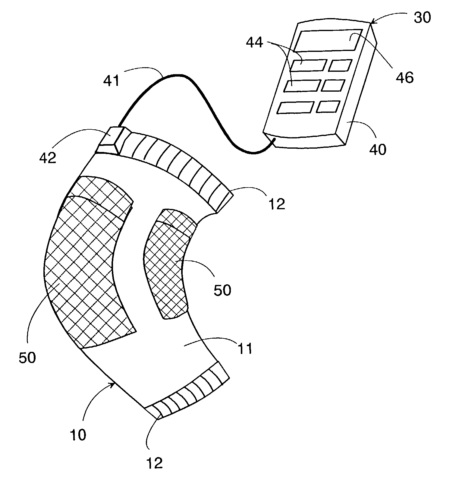
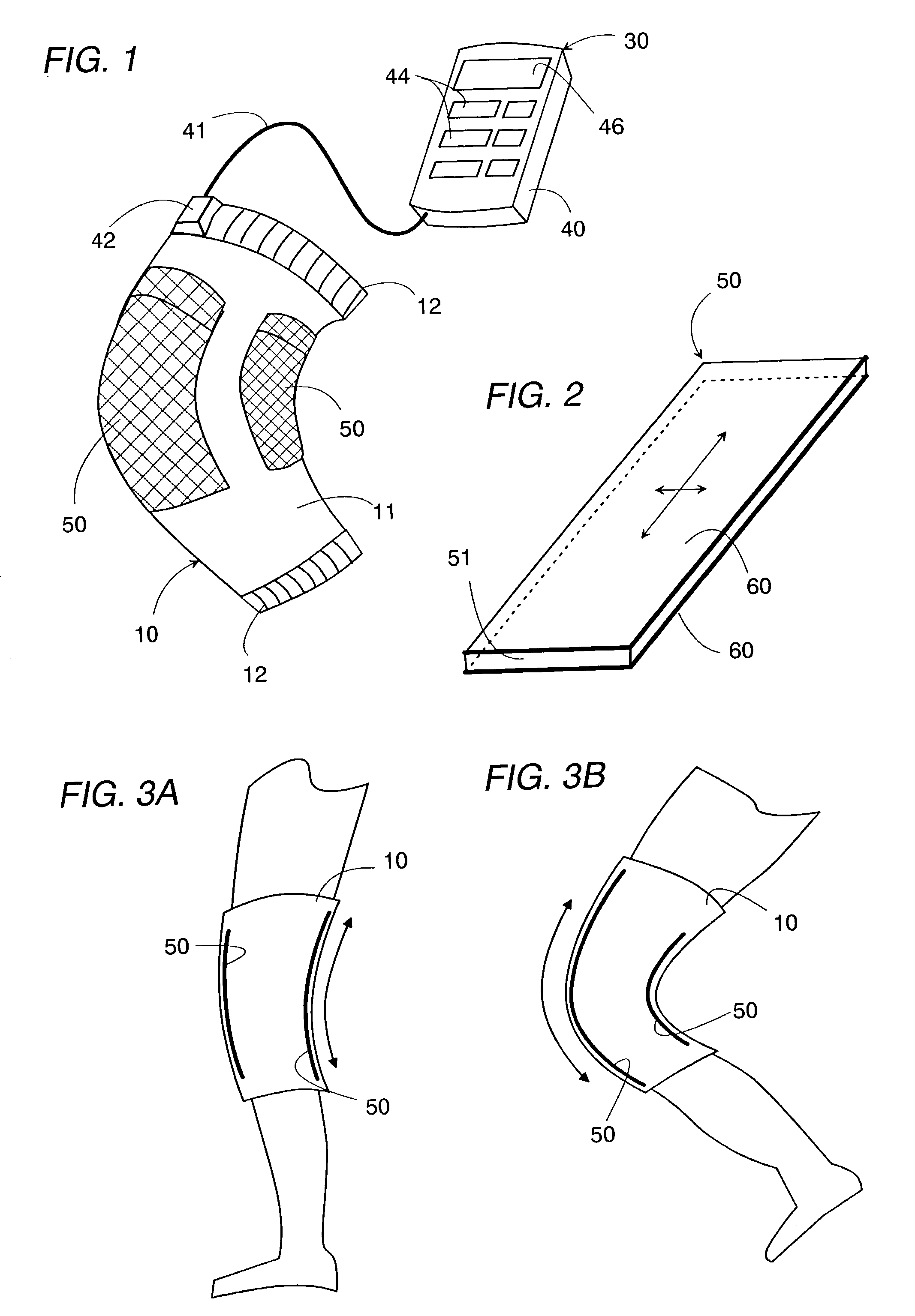
[0050]Referring now to FIG. 1, there is shown a wearable human motion applicator in accordance with the present invention. The applicator includes a flexible support 10 carrying a pair of electro-active elastic actuators 50, and a controller 30 carried on a user, for example, attached to clothing of the user or placed in a pocket of the clothing. The flexible support 10 includes a main body 11 of a stretchable fabric adapted to be fitted around a part such as a knee joint of the human body and includes fasteners 12 for tightly holding the support 10 around the part. The main body 11 may be fabricated into a sleeve or bandage as shown in FIG. 8. The actuator 50 is generally known as the electrostrictive polymer actuator and is composed of a dielectric core 51 made of an elastomeric polymer such as acrylic elastomer and silicone, and a pair of flexible electrodes 60 on opposite surfaces of the core. As shown in FIG. 2, the actuator 50 of the present embodiment is provided in the form ...

third embodiment

[0059]FIG. 10 shows the present invention which is designed to reduce distortion about a spine of the human body and includes a cylindrical torso support 10B wrapped around a torso of the human body. The torso support 10B is made from a flexible material and carries a pair of like actuators 50B which are shaped into bands extending circumferentially about a lengthwise axis of the support and crossing with each other on back of the support. Also carried on the support 10B are four sensors 20B which are provided respectively at portions corresponding to the opposite ends of each actuator 50B so as to obtain amounts of strains of the torso respectively about the lengthwise axis as well as about a horizontal axis perpendicular to the lengthwise axis. The output of the sensors 20B are processed by a like motion analyzer as utilized in the embodiment of FIG. 4 to give a strain signal indicative of the amounts of the strains. A like controller is included in this embodiment to give the dri...

fourth embodiment

[0061]FIGS. 12 to 14 show the present invention which is designed to give a massaging action to a lower limb of the human body, and includes a flexible tubular support 10D fitted around the lower limb adjacent a calf. In this embodiment, the support 10D carries a single elastic actuator 50D of a tubular configuration formed on the interior and exterior surfaces respectively with flexible electrodes. The tubular actuator 50D expands in a radial direction upon receiving the increasing driving DC voltage across the electrodes and contracts as the DC voltage decreases. Thus, it is made to repeat generating and releasing a pressing force applied to the lower limb of the human body for giving a massaging action thereto.

[0062]For this purpose, the controller 30D includes a random signal generator 39D which generates a random signal which is fed through a multiplier 47D to a voltage generator 48D where the signal is processed to provide the driving DC voltage of a suitable level to be suppl...


PUM


Abstract

An improved human motion applicator assures a quick and sufficient amount of displacement given to a part of a human body. The applicator includes a support adapted to be fitted on the part of the human body. The support carries at least one electro-active elastic actuator in a force-transmitting relation to the human part. The actuator includes a dielectric core and a pair of electrodes on opposite of the core for receiving a driving DC voltage thereacross. The elastic actuator has a length and elastically deforms in the lengthwise direction to exert a stretching force to the human part to a greater extent as the driving DC voltage increase. The applicator also includes a controller which applies the driving DC voltage of varying levels to the elastic actuator, thereby generating a varying motion-inducing force to be applied to the part of the human body.

Description

TECHNICAL FIELD[0001]The present invention is directed to a wearable human motion applicator, and more particularly to a human motion assisting or inducing device utilizing an electro-active elastic actuator.BACKGROUND ART[0002]Human motion applicator is proposed in Japanese Patent Early Publication No. 2002-48053 which utilizes a memory shape alloy which deforms in response to heat generated by application of electric current for giving a stretching or contracting force to thereby assist a motion intended by a human body. However, due to a limitation to the amount of the displacement and a response speed given to the memory shape alloy, the prior art motion applicator is found insufficient in that it is not completely in match with an actual need of assisting or inducing the human motion.DISCLOSURE OF THE INVENTION[0003]The above insufficiency has been reduced in the present invention which provides an improved human motion applicator which assures a quick and sufficient amount of ...

Claims


Application Information

Patent Timeline
Patent Type & Authority Patents(United States)
IPC IPC(8): A61H1/00A61F2/58A61F2/64A63B23/00A63B24/00G06F3/00G06F3/01H01L41/09
CPCA63B21/00181A63B23/00G06F3/016A63B24/00H01L41/0986A63B2230/60H10N30/206A61F2/50
Inventor DOHNO, SHIGERUYUASA, SHINGOSAITO
Owner MATSUSHITA ELECTRIC WORKS LTD
Why Eureka
Try Eureka