
Ethernet connectors

Inactive Publication Date: 2008-11-06
SHNAJDER ELEKTRIK GMBKH
View PDF10 Cites 9 Cited by
  • Summary
  • Abstract
  • Description
  • Claims
  • Application Information

AI Technical Summary

Benefits of technology

[0010]Using separate IA device for LAN and WLAN may create barriers to acceptance as a result of real or perceived differences in the device's application functionality. Capability of adapting the same Ethernet-enabled device to a new wireless connectivity rather than replacing it with a separate device would eliminate such concerns.
[0014]Every IA device with the new RJ45 connector can be easily upgraded to WLAN.

Problems solved by technology

Using separate IA device for LAN and WLAN may create barriers to acceptance as a result of real or perceived differences in the device's application functionality.

Method used


Image

  • Ethernet connectors
  • Ethernet connectors
  • Ethernet connectors

Examples


Embodiment Construction

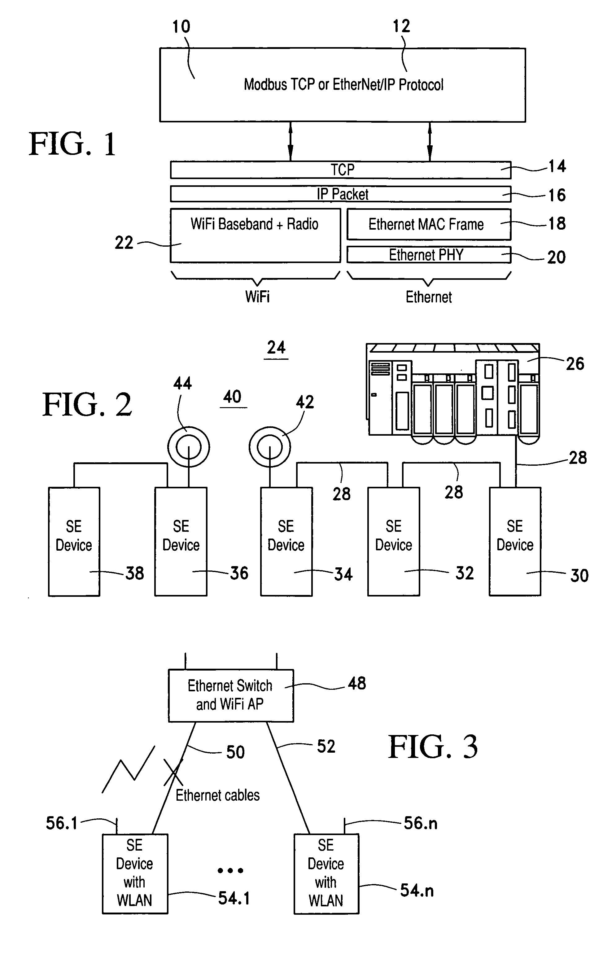
[0026]FIG. 2 shows a simple example of an IA system 24 providing combined Ethernet and WLAN connectivity at the device level. A control unit 26 is connected to SE Devices 30, 32, 34 via a LAN-connection. Further SE Devices 36, 38 are coupled to control unit 26 via a WLAN connection, said SE Devices 34, 36 each having a WLAN unit 42, 44.

[0027]The same device that is typically used in an Ethernet Daisy Chain (DC) topology may occasionally need to be extended to connect wirelessly over one or more segments of the chain.

[0028]FIG. 3 shows another IA application comprising an Ethernet switch with WiFi 48 which is connected over Ethernet cables 50, 52 to SE Devices 54.1-54.n with WLAN 56.1-56.n. The WLAN 56.1-56.n serves as a redundancy connection.

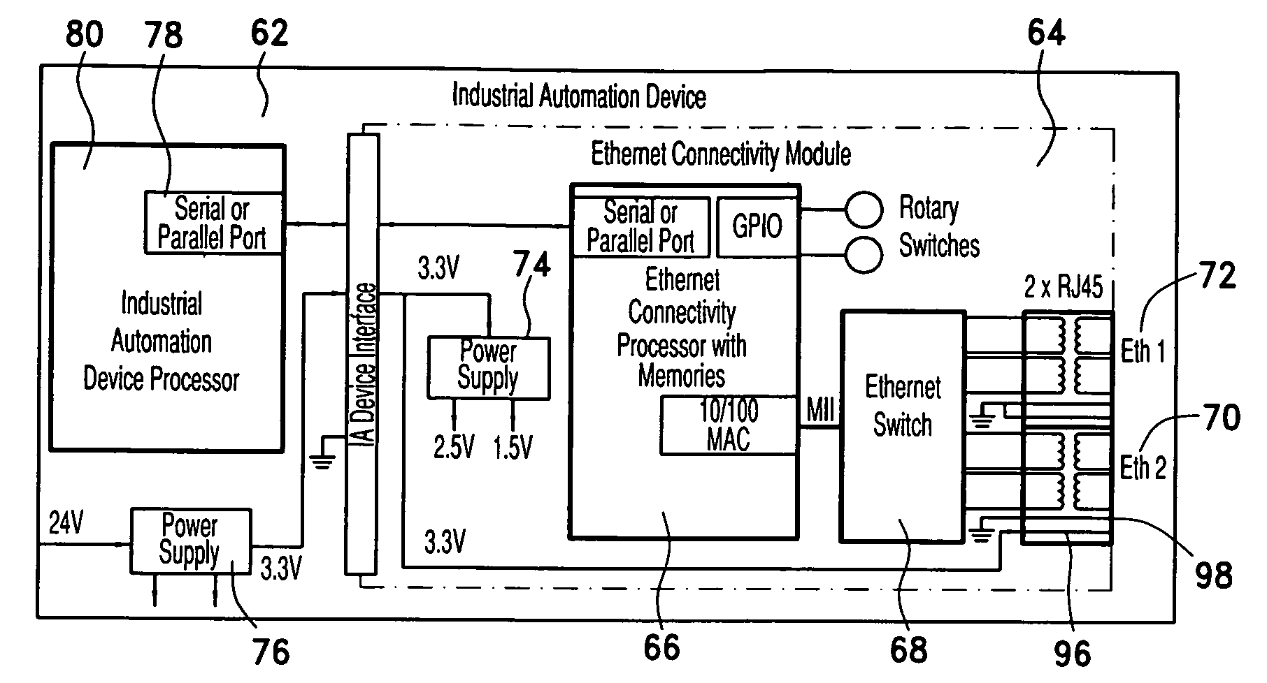
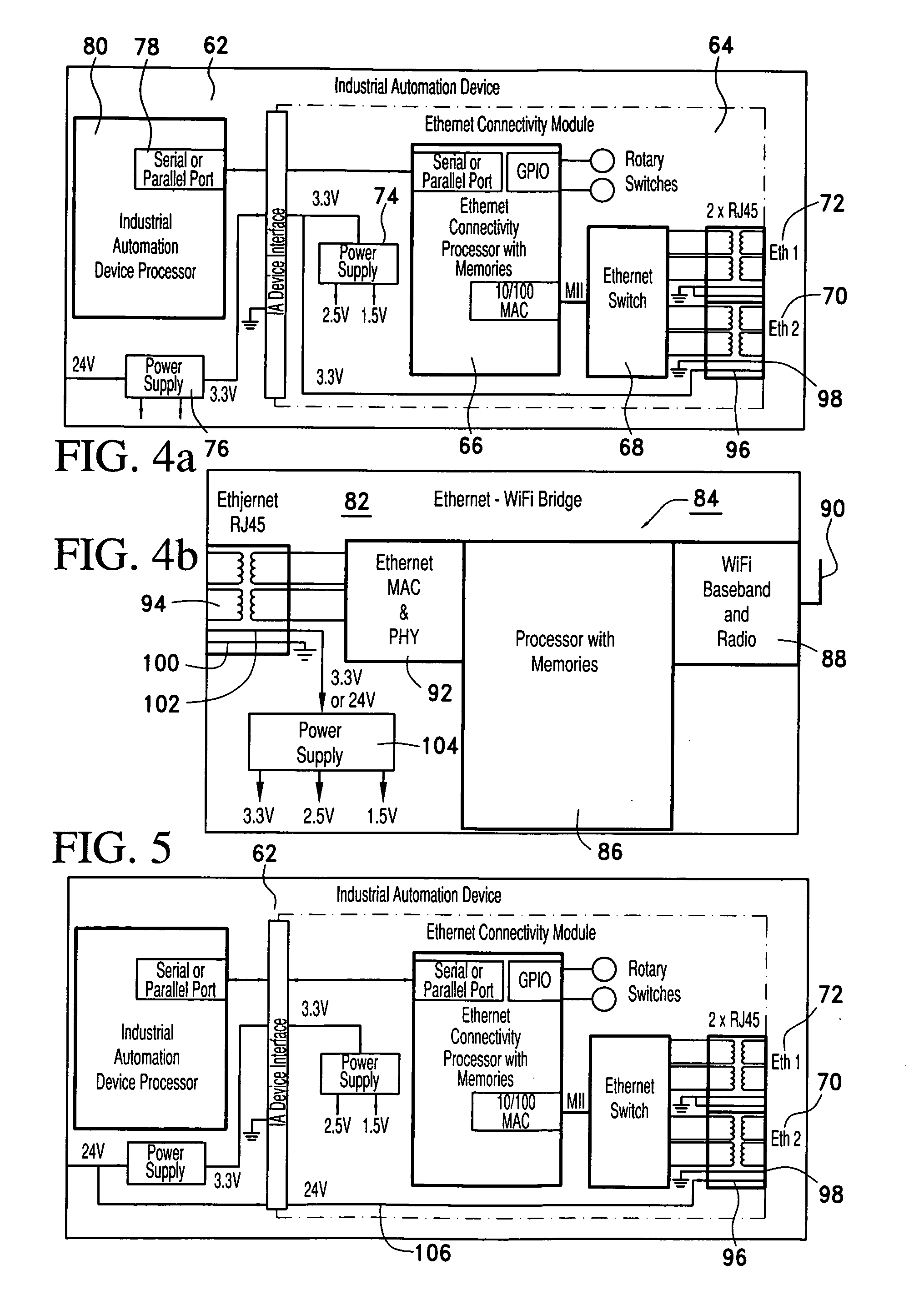
[0029]FIG. 4a shows purely in principal the design of an industrial automation device 62 with an Ethernet connectivity module 64. The Ethernet connectivity module 64 comprises an Ethernet connectivity processor 66 with memories being connected t...


PUM


Abstract

A modular ethernet-connector includes a jack (70) as part of a device (62) such as industrial automation device with embedded Ethernet connectivity (66), and a corresponding plug, the plug (94) being part of a WLAN-stick (82) which includes an embedded Ethernet-WLAN-Bridge (84).

Description

[0001]This application claims the benefit of U.S. Provisional Application Ser. No. 60 / 915,972 filed May 4, 2007, the contents of which are incorporated herein by reference.FIELD OF THE INVENTION[0002]The invention relates to a Modular Ethernet-Connector, comprising a jack as part of a device such as industrial automation device with embedded Ethernet connectivity and a corresponding plug to connect the device with the Ethernet.BACKGROUND OF THE INVENTION[0003]Devices in Industrial Automation (IA) markets have been traditionally connecting using industrial protocols running over industrial fieldbuses. In recent years, new trend evolved where the traditional fieldbuses are being replaced by industrial protocols 10, 12 running on standard Internet Protocols (IP) 1416, commonly called TCP / IP protocols, and using standard Internet infrastructure, as shown in FIG. 1. The most prevalent has been Ethernet twisted Copper pair infrastructure. As a result, many IA devices use standard RJ45 Eth...

Claims


Application Information

Patent Timeline
IPC IPC(8): H01R13/66
CPCH01Q1/2266H01Q1/2275H04L12/2856H04L12/4625
Inventor SCHOOP, RONALDREISS, WANDA
Owner SHNAJDER ELEKTRIK GMBKH
Learn More