
System and methods for optimal light collection array

Active Publication Date: 2008-11-13
RAYTHEON CO
View PDF20 Cites 17 Cited by
  • Summary
  • Abstract
  • Description
  • Claims
  • Application Information

AI Technical Summary

Benefits of technology

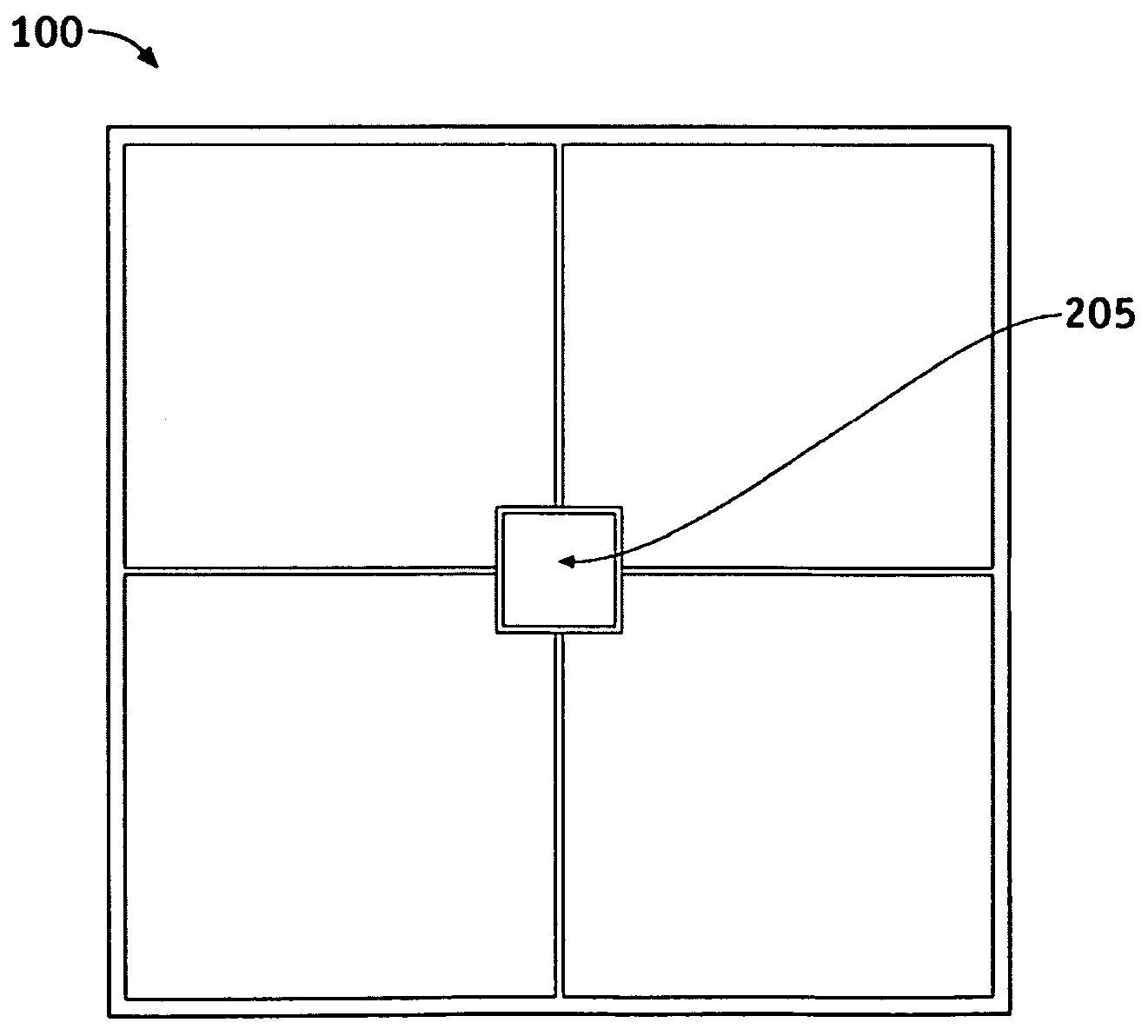
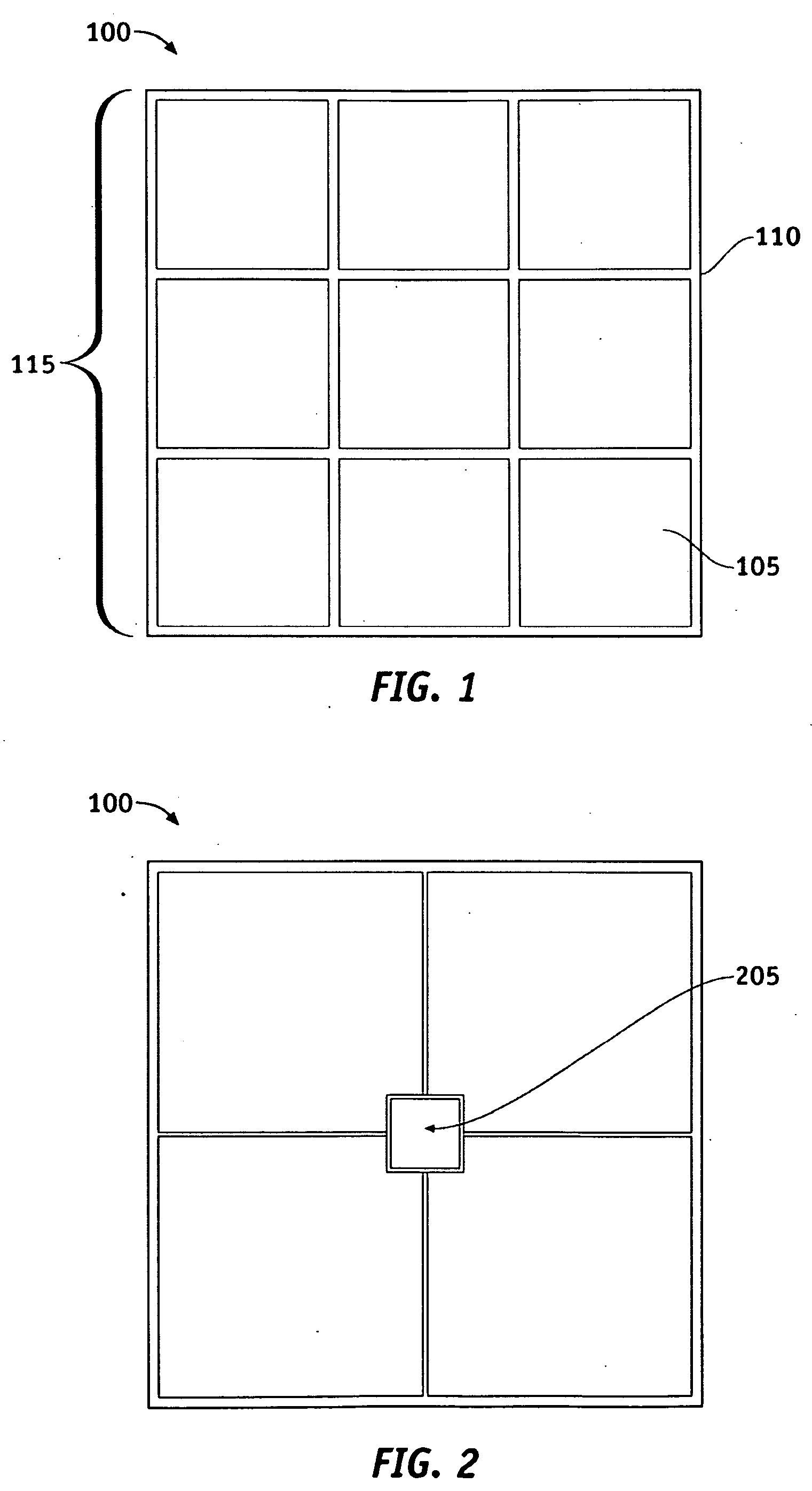
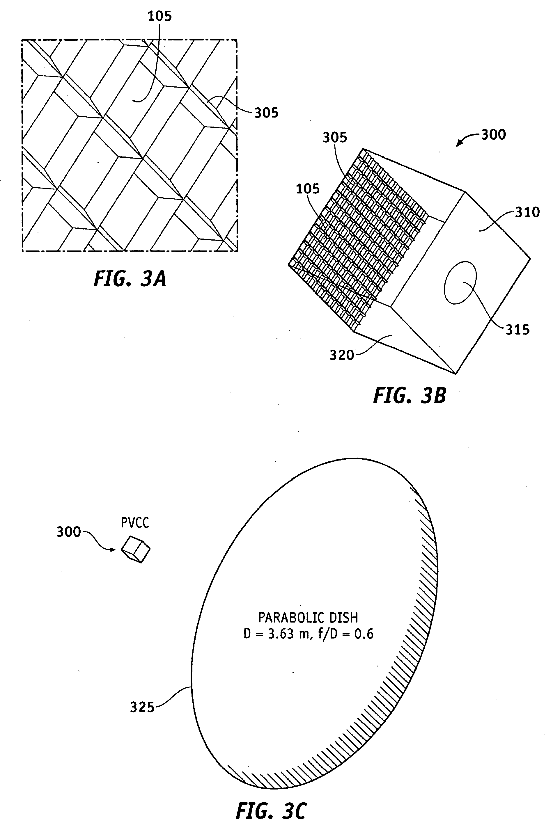
[0005]Apparatus and methods according to various aspects of the present invention may operate in conjunction with a light collection array. One or more light redirectors located at or near inactive areas of the li

Problems solved by technology

The implementation of multiple photovoltaic cells presents several challenges.
Because the inactive area generally includes the edge of a cell, the active areas of the cells cannot be placed adjacent to each other, causing a grid-like area where light is either absorbed or reflected and cannot be converted to electrical energy.
The current produced, however, tends to be limited by the cell illuminated by the least amount of light in a series string of photovoltaic cells.

Method used


Image

  • System and methods for optimal light collection array
  • System and methods for optimal light collection array
  • System and methods for optimal light collection array

Examples


Embodiment Construction

[0016]The present invention may be described in terms of functional block components and various processing steps. Such functional blocks may be realized by any number of elements configured to perform the specified functions and achieve the various results. For example, the present invention may employ various photovoltaic arrays, light redirectors, reflective materials and the like, which may carry out a variety of functions. In addition, the present invention may be practiced in conjunction with any number of light collection applications, and the system described is merely one exemplary application for the invention. Further, the present invention may employ any number of conventional techniques for manufacturing reflective materials, photovoltaic arrays, light redirectors, and the like.

[0017]Methods and apparatus according to various aspects of the present invention may be implemented in conjunction a light redirector and a target area. The light redirector redirects light to t...


PUM


Abstract

Apparatus and methods according to various aspects of the present invention may operate in conjunction with a light collection array. One or more light redirectors located at or near inactive areas of light collection arrays may redirect incident light to active areas. In one embodiment, the light redirector may be implemented with additional light redirectors and / or a concentrating photovoltaic collection system.

Description

CROSS REFERENCE TO RELATED APPLICATIONS[0001]The present application is a continuation-in-part of U.S. Nonprovisional patent application Ser. No. 11 / 733,544, filed Apr. 10, 2007, entitled Concentrating Photovoltaic Kaleidoscope and Method, and incorporates the disclosure of such application by reference.BACKGROUND OF INVENTION[0002]Photovoltaic cells convert solar energy into electrical energy to power various applications, from handheld calculators and street signs to water pumping applications and large grid-tied electrical systems. Photovoltaic cells are particularly useful, however, in remote and extra-orbital applications where grid electricity is not available. Individual photovoltaic cells are generally implemented for smaller applications, such as handheld calculators. Larger applications, such as grid-tied solar panels and photovoltaic panels powering satellites, require multiple cells to generate electrical energy needed.[0003]The implementation of multiple photovoltaic ce...

Claims


Application Information

Patent Timeline
IPC IPC(8): H01L31/042
CPCH01L27/1446H01L31/0547Y02E10/52
Inventor JORDAN, MEAD M.JENKINS, DAVID G.CROWE, DEVON G.
Owner RAYTHEON CO
Learn More