
Vibration actuator

a technology of vibration actuator and actuator body, which is applied in the direction of piezoelectric/electrostrictive/magnetostrictive devices, piezoelectric/electrostriction/magnetostriction machines, electrical apparatus, etc., can solve the problems affecting the driving direction of the actuator, and affecting the reaction force. , to achieve the effect of reducing the efficiency of the vibration actuator

Inactive Publication Date: 2008-11-13
PANASONIC CORP
View PDF6 Cites 14 Cited by
  • Summary
  • Abstract
  • Description
  • Claims
  • Application Information

AI Technical Summary

Benefits of technology

[0006]Although the vibration actuator of Japanese Unexamined Patent Publication No. 8-191575 is elastically supported only in the direction toward the movable body, it is inelastically supported in one of driving directions in which the driver element outputs the driving force. As a result, the vibration of the actuator body in the driving direction is hindered and the efficiency of the vibration actuator may be reduced.
[0007]Therefore, supporting the actuator body elastically along the driving direction is considered as a solution to this problem. With this configuration, the actuator body is supported without hindering the vibration of the actuator body in the driving direction.
[0010]The present invention has been achieved in view of the above-described problem. An object of the invention is to realize a structure for supporting an actuator body which does not hinder the vibration of the actuator body in the driving direction and makes it possible to output a sufficient driving force even if a large reaction force is exerted on the driver element.

Problems solved by technology

As a result, the vibration of the actuator body in the driving direction is hindered and the efficiency of the vibration actuator may be reduced.
On the other hand, if the driving load is large, the reaction force also becomes large.
Therefore, the reaction force cannot be received by the elastic support and the driving force is not output appropriately to the movable body.
Therefore, the magnitude of the driving force is limited.

Method used


Image

  • Vibration actuator
  • Vibration actuator
  • Vibration actuator

Examples


Embodiment Construction

[0028]Hereinafter, an embodiment of the present invention will be described with reference to the drawings.

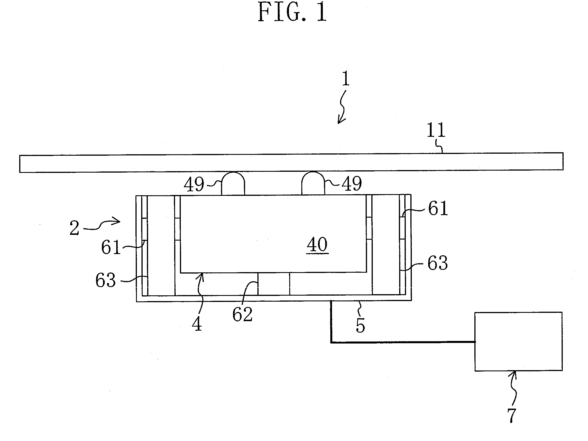
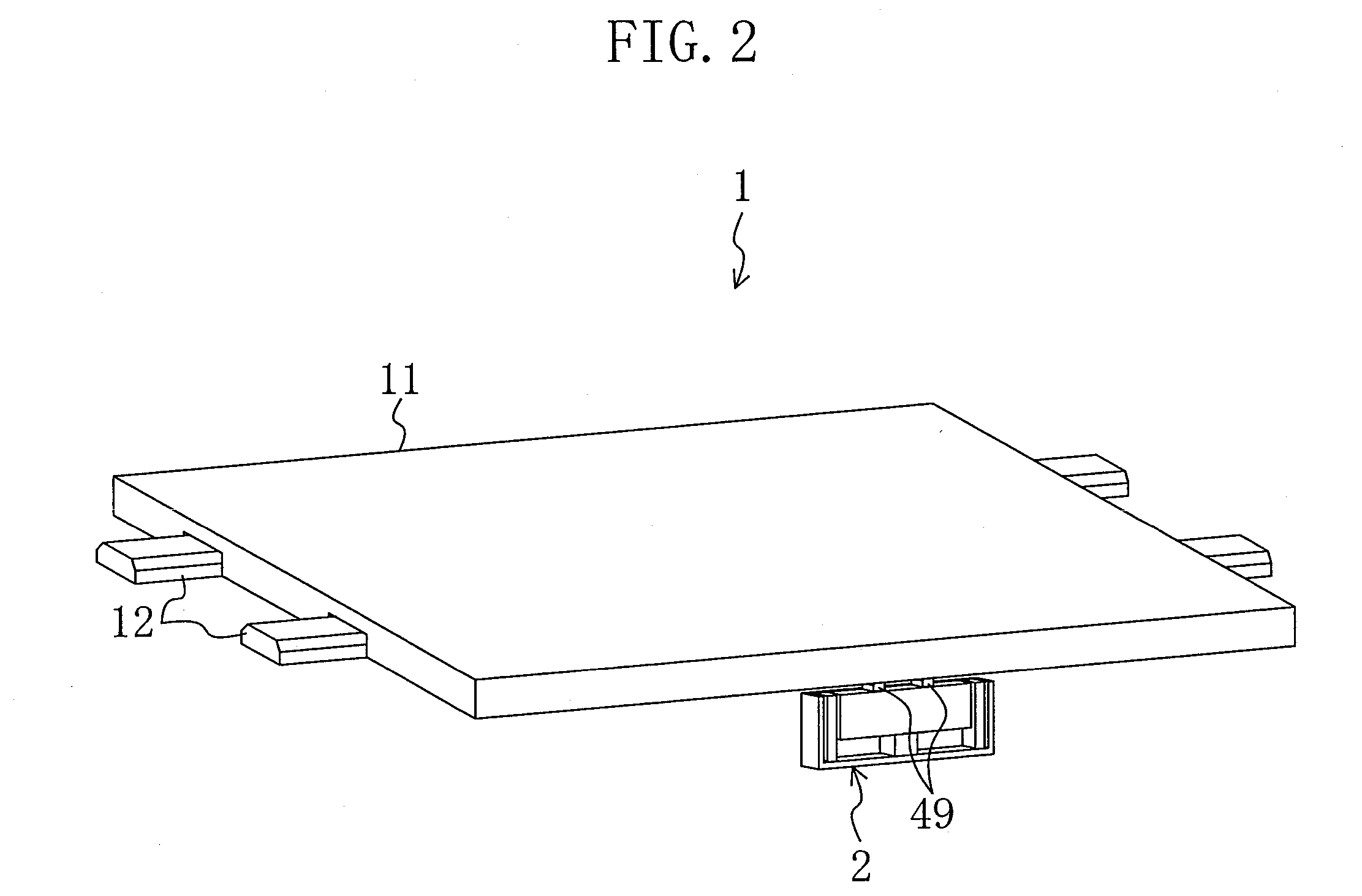
[0029]A drive unit 1 according to an embodiment of the invention includes, as shown in FIGS. 1 and 2, a stage 11, an ultrasonic actuator 2 and a control unit 7 for controlling and driving the ultrasonic actuator 2.

[0030]The stage 11 is slidably attached to guides 12 fixed in parallel with each other to a base (not shown) as a stationary body. That is, the stage 11 is movable in the extending direction of the guides 12 (the extending direction of the guides 12 is the moving direction of the stage 11). The stage 11 is a plate-like member and substantially square-shaped when viewed in plan. The ultrasonic actuator 2 is arranged such that driver elements 49 described later come into contact with the rear surface of the stage 11 (the surface on which the guides 12 are provided).

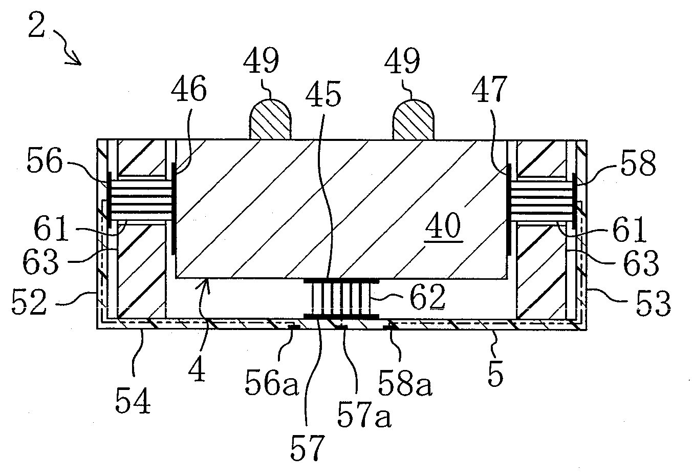
[0031]The ultrasonic actuator 2 includes, as shown in FIG. 3, an actuator body 4 which generates vibration...


PUM


Abstract

An ultrasonic actuator includes: an actuator body using a piezoelectric element and generating a plurality of vibrations of different vibration directions; a driver element provided in the actuator body and operated in accordance with the vibration of the actuator body to output a driving force in a predetermined driving direction; a case containing the actuator body; at least one support rubber provided between the actuator body and the case to elastically support the actuator body along the driving direction with respect to the case; and at least one stopper provided between the actuator body and the case which comes into contact with at least one of the actuator body and the case when the actuator body is displaced in a direction opposite the driving direction such that the displacement of the actuator body in the direction opposite the driving direction is limited.

Description

BACKGROUND OF THE INVENTION[0001]1. Field of the Invention[0002]The present invention relates to a vibration actuator including an actuator body using a piezoelectric element and generating a plurality of vibrations of different vibration directions.[0003]2. Description of Related Art[0004]A vibration actuator including an actuator body using a piezoelectric element has been known (cf., Japanese Unexamined Patent Publication No. 8-191575) and used in ultrasonic motors and devices which make small step-by-step displacement.[0005]The actuator body includes the piezoelectric element and generates a plurality of vibrations including longitudinal and bending vibrations in harmony by vibrating the piezoelectric element. The actuator body is elastically supported in a direction toward a movable body and a driver element of the actuator body is in contact with the movable body with pressure applied thereto. That is, when the actuator body generates the longitudinal and bending vibrations in...

Claims


Application Information

Patent Timeline
Patent Type & Authority Applications(United States)
IPC IPC(8): H02N2/02H01L41/053
CPCH01L41/053H01L41/0906H02N2/004H02N2/026H10N30/88H10N30/2023H02N2/0055
Inventor HIGASHIONJI, MASARUMUKAE, HIDEAKIADACHI, YUSUKENAGAOKA, EIICHI
Owner PANASONIC CORP
Learn More