Fixing apparatus for hard disk drive

Active Publication Date: 2008-11-13
FULIAN PRECISION ELECTRONICS (TIANJIN) CO LTD
View PDF2 Cites 28 Cited by
  • Summary
  • Abstract
  • Description
  • Claims
  • Application Information

AI Technical Summary

Problems solved by technology

For proper balanced installation of the HDD, multiple screws should be fastened

Method used


Image

  • Fixing apparatus for hard disk drive
  • Fixing apparatus for hard disk drive
  • Fixing apparatus for hard disk drive

Examples


Example

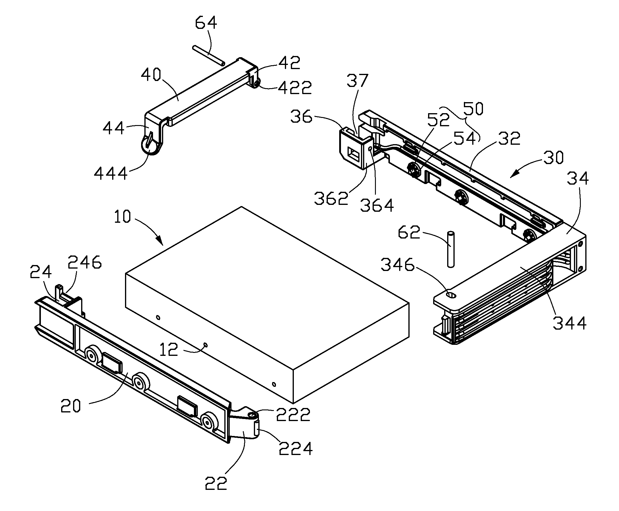
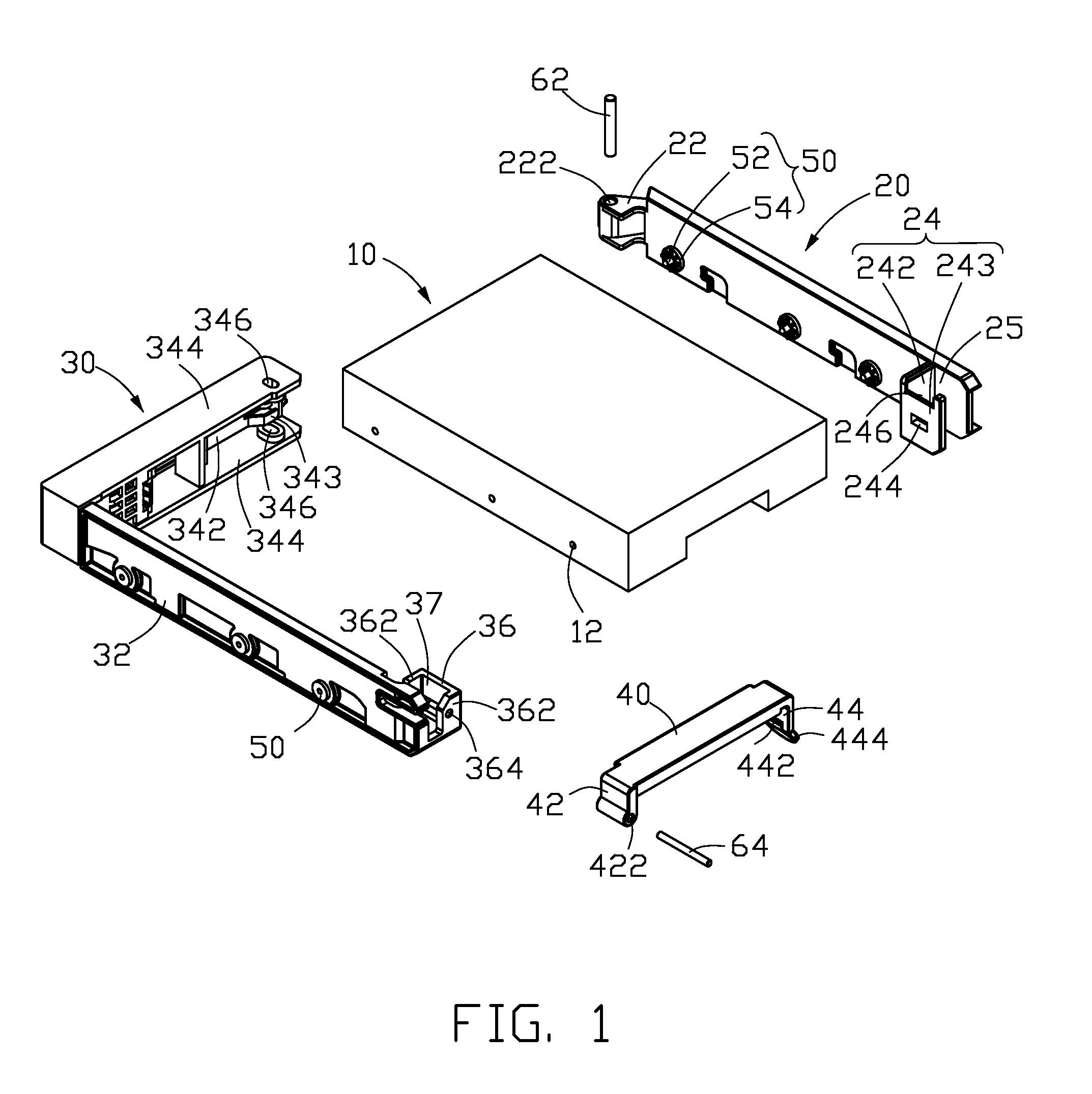
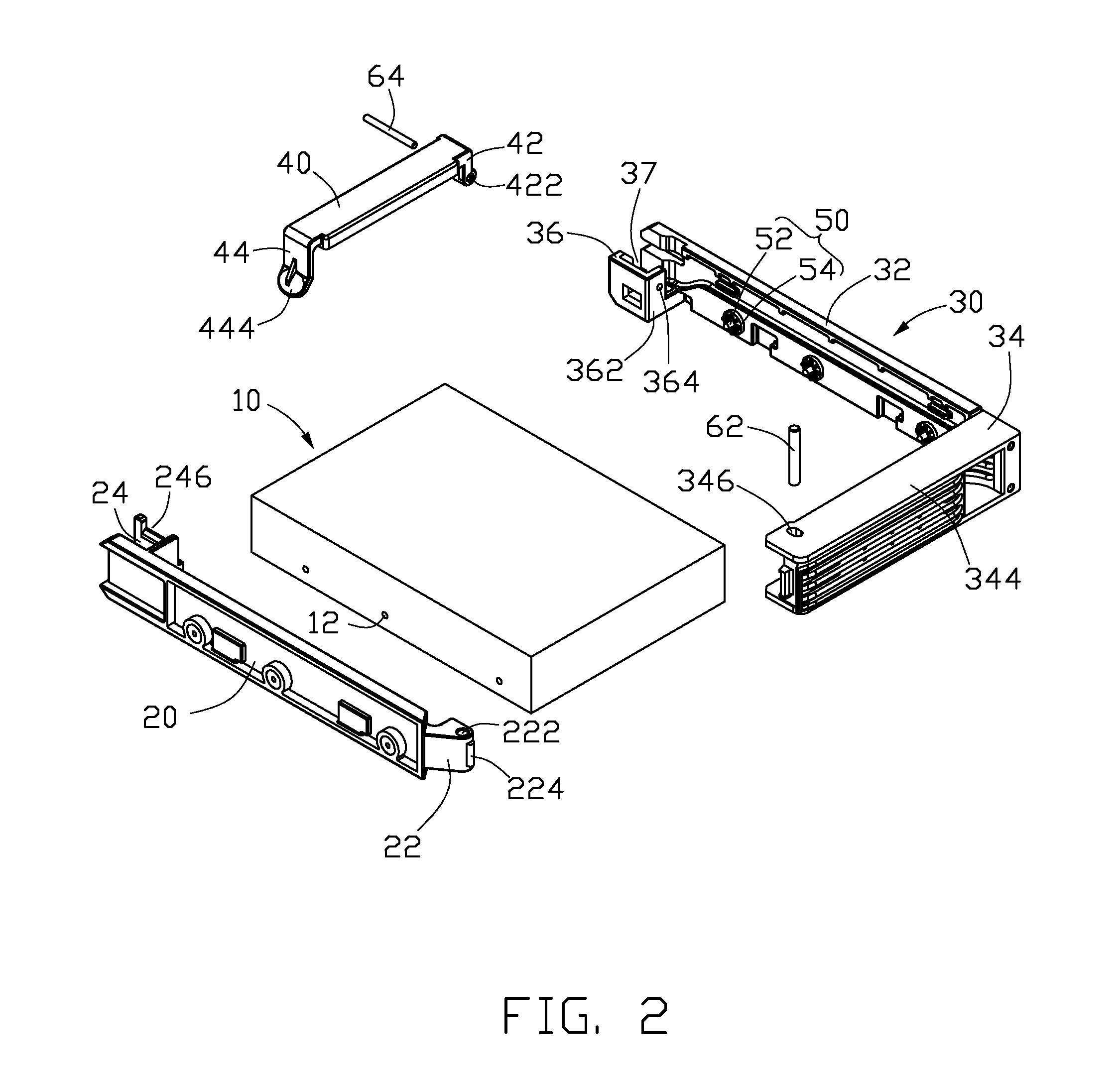
[0011]Referring to FIGS. 1 and 2, a fixing apparatus in accordance with an embodiment of the present invention is for fixing a hard disk drive (HDD) 10 and includes a first fixing plate 20, a bracket 30, a transverse bar 40, and two shafts 62, 64.

[0012]The HDD 10 includes a pair of holes 12 defined in each of two opposite sidewalls thereof.

[0013]The first fixing plate 20 includes a pivoting portion 22 extending slantingly and inward from one end thereof, and a locking portion 24 formed at an inside of the other end thereof. The pivoting portion 22 includes a pivoting hole 222 defined in a free end thereof, and a semi-cylindrical protrusion 224 formed at the outside surface of the free end. The locking portion 24 includes a first wall 242 perpendicular to the first fixing plate 20, and a second wall 243 parallel to the first fixing plate 20 and perpendicularly connecting to the first wall 242. The locking portion 24 and the first fixing plate 20 cooperatively define a receiving space...


PUM


Abstract

An exemplary fixing apparatus is for mounting a hard disk drive having a plurality of holes in sidewalls thereof. The fixing apparatus includes a first fixing plate, a bracket, and a transverse bar. The bracket includes a second fixing plate, and a bezel assembly attached to a first end of the second fixing plate. Each of the first fixing plate and the second fixing plate include a plurality of fixing members formed at inside walls thereof to engage in the holes of the disk drive. The first fixing plate is pivotally attached to a free end of the bezel assembly. One end of the transverse bar is pivotally attached to a second end of the second fixing plate opposite to the first end and the other end of the transverse bar detachably engages with the first fixing plate.

Description

BACKGROUND[0001]1. Field of the Invention[0002]The present invention relates to fixing apparatuses, and particularly to a fixing apparatus for hard disk drives (HDD).[0003]2. Description of Related Art[0004]The conventional approach now being adopted to mount an HDD in a computer chassis generally involves placing the HDD in a holding area of a drive bracket; screwing a plurality of screws through side walls of the drive bracket into two sides of the HDD to fasten the HDD on the drive bracket; and mounting the HDD and the bracket in a computer chassis or a mobile HDD rack. For proper balanced installation of the HDD, multiple screws should be fastened at the same time, making installing and removing operations of the HDD tedious.[0005]What is desired, therefore, is a fixing apparatus which allows convenient installation and removal of an HDD.SUMMARY[0006]An exemplary fixing apparatus is for mounting an HDD having a plurality of holes in sidewalls thereof. The fixing apparatus includ...

Claims


Application Information

Patent Timeline
IPC IPC(8): G11B21/16
CPCG11B33/124G11B33/128
Inventor PENG, WEN-TANGGONG, XIN-HU
Owner FULIAN PRECISION ELECTRONICS (TIANJIN) CO LTD
Why Eureka
Try Eureka