Perpendicular magnetic recording head

a magnetic recording head and perpendicular technology, applied in the field of perpendicular magnetic recording head, can solve the problems of magnetic field intensity, difficult for conventional structures deterioration of total recording performance, so as to suppress side fringing, keep recording magnetic field intensity from decreasing, suppress side fringing

Active Publication Date: 2008-11-13
TDK CORPARATION
View PDF2 Cites 21 Cited by
  • Summary
  • Abstract
  • Description
  • Claims
  • Application Information

AI Technical Summary

Benefits of technology

[0009]It is an object of the present invention to provide a perpendicular magnetic recording head which can suppress side fringing while keeping the recording magnetic field intensity from decreasing.
[0011]In this structure, at least the first gap layer separates the pair of side shield layers from the return yoke layer in the vicinity of the trailing edge of the main magnetic pole layer, so that the magnetic path length from the trailing edge of the main magnetic pole layer to the pair of side shield layers becomes longer than that in the case where the pair of side shield layers are not separated from the return yoke layer, whereby recording magnetic fluxes are harder to be absorbed by the pair of side shield layers. This can keep the recording magnetic field intensity from decreasing. Except for the vicinity of the trailing edge of the main magnetic pole layer, the second gap layer is interposed between the return yoke layer and the pair of side shield layers, so that leakage magnetic fields are easier to occur than in the case where the first gap layer is interposed. Therefore, side magnetic fluxes leaking from the main magnetic pole layer are easier to be absorbed by the pair of side shield layers than in the case where the pair of side shield layers are completely separated from the return yoke layer, whereby side fringing can be suppressed. The amount of magnetic fluxes (amount of recording magnetic fluxes or amount of side magnetic fluxes) absorbed by the pair of side shield layers can be adjusted by the size of the first gap layer in the track width direction and the thickness of the second gap layer.
[0018]In the present invention, at least the first gap layer separates the pair of side shield layers from the return yoke layer in the vicinity of the main magnetic pole layer, so that recording magnetic fluxes directed from the main magnetic pole layer to the recording medium are hard to be absorbed by the pair of side shield layers, whereby the recording magnetic field intensity can be kept from decreasing. At the same time, the pair of side shield layers are in contact with the return yoke layer through the second gap layer thinner than the first gap layer in the remaining area in the track width direction where the first gap layer is absent, so that side magnetic fluxes leaking from the main magnetic pole layer are easy to be absorbed by the pair of side shield layers, whereby side fringing can be suppressed. This yields a perpendicular magnetic recording head which can suppress side fringing while keeping the recording magnetic field intensity from decreasing.

Problems solved by technology

This causes a fear of recording actions failing for recording media having a high coercivity, whereby the total recording performance will deteriorate even if the recording magnetic field gradient improves.
Thus, it has been difficult for the conventional structures to suppress side fringing while keeping the recording magnetic field intensity from decreasing.

Method used


Image

  • Perpendicular magnetic recording head
  • Perpendicular magnetic recording head
  • Perpendicular magnetic recording head

Examples


first embodiment

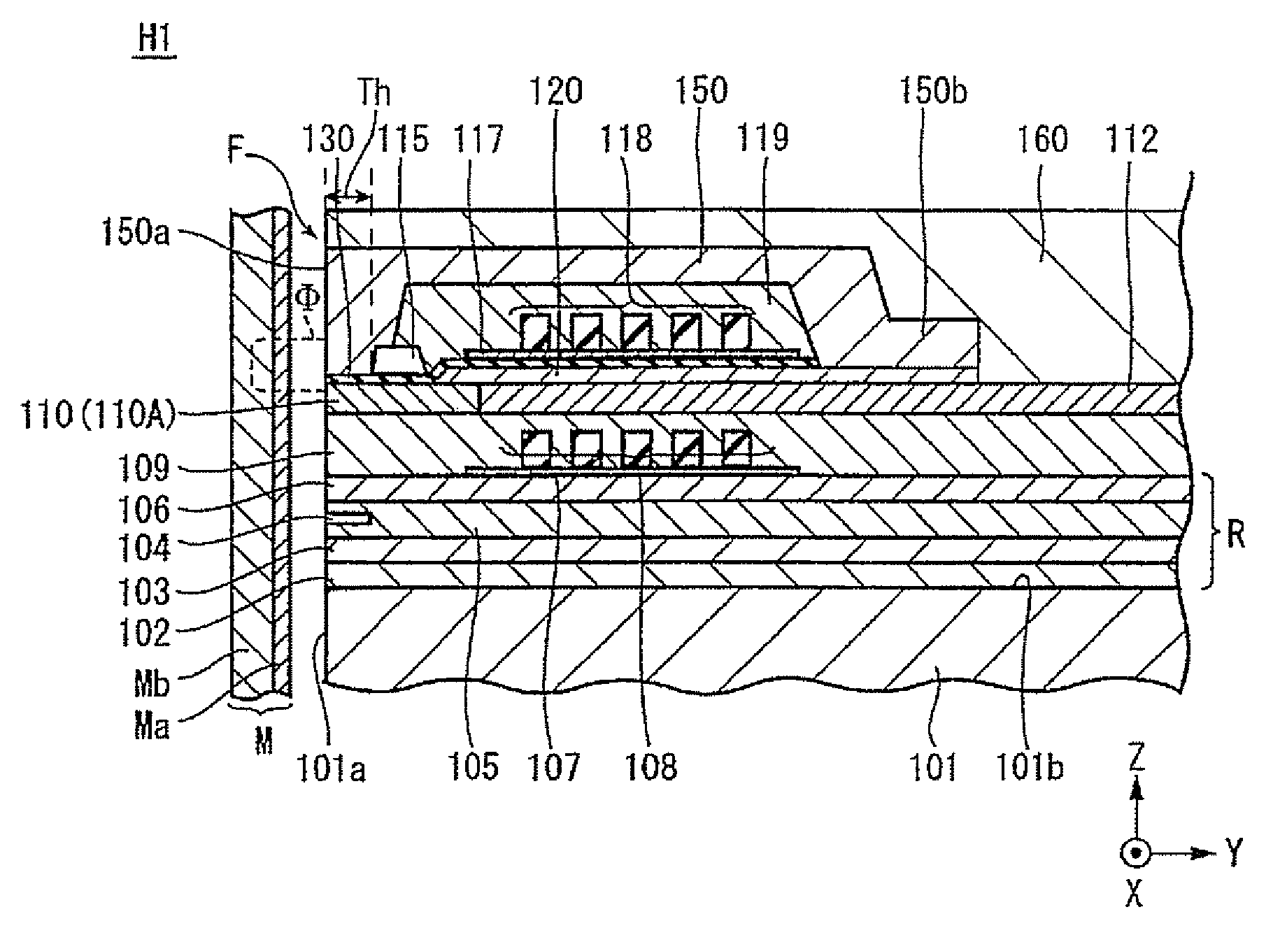
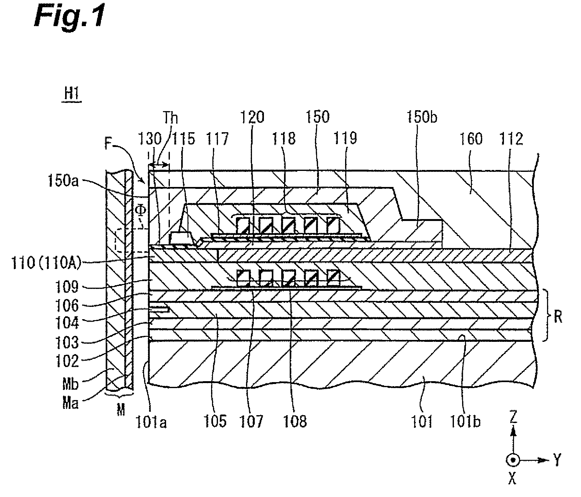
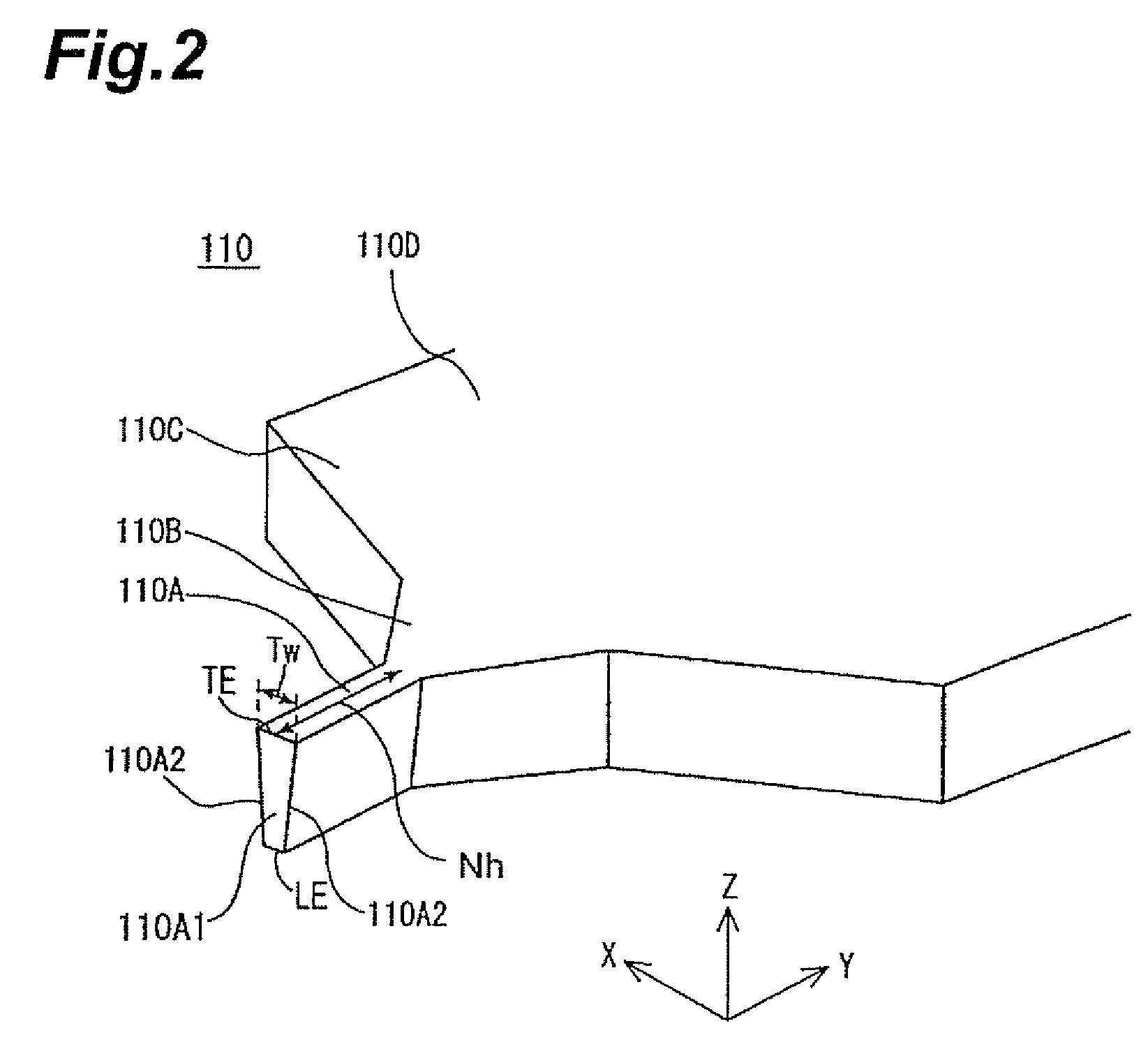
[0031]FIG. 1 is a vertical sectional view showing the multilayer structure of the perpendicular magnetic recording head H1 in accordance with the present invention, while FIG. 2 is a perspective view for explaining a main magnetic pole form.

[0032]The perpendicular magnetic recording head H1 provides a recording medium M with a recording magnetic flux Φ perpendicular thereto, thereby perpendicularly magnetizing a hard film Ma of the recording medium M. The recording medium M has the hard film Ma with a higher remanent magnetization on the medium surface side and a soft film Mb with a higher magnetic permeability on the inner side of the hard film Ma. The recording medium M is shaped like a disk, for example, and is rotated about the center of the disk as a rotary axis. A slider 101 is formed by a nonmagnetic material such as Al2O3.TiC. The slider 101 has a medium-opposing surface 101a opposing the recording medium M. As the recording medium M rotates, a surface airflow levitates the ...

second embodiment

[0065]In the second embodiment, the upper faces of the pair of side shield layers 200 are positioned lower than the trailing edge TE of the main magnetic pole layer 110 in the drawing, so that the pair of side shield layers 200 are located more on the leading edge side of the main magnetic pole layer 110 and harder to be involved with the recording magnetic flux released from the trailing edge TE of the main magnetic pole layer 110. The upper face position of the pair of side shield layers 200 can be adjusted by the thickness d2 of the second gap layer 132. At the time of skewing, the slider 101 is tilted, whereby side fringing can be suppressed by reducing the side magnetic fluxes generated from the leading edge LE side of both side faces 110A2 of the magnetic pole part 110A even when the side magnetic fluxes generated from the side faces 110A2 are not completely eliminated.

[0066]By adjusting the thickness d2 of the second gap layer 132, the second embodiment can change the upper f...

third embodiment

[0091]The foregoing steps yield the pair of side shield layers 200, first and second gap layers 131, 132, and return yoke layer 150 shown in FIG. 7. In the third embodiment, the part of side shield layers 200 positioned directly below the part of first gap layer 131 outside of the width W1 is removed together with the latter in the etching step for defining the width W1 of the first gap layer 131, whereby the size of the pair of side shield layers 200 in the track width direction is determined according to the width W1 of the first gap layer 131.

[0092]FIGS. 9 and 10 show a fourth embodiment of the present invention. FIG. 9 is a transverse sectional view showing the multilayer structure of a perpendicular magnetic recording head H4 as seen from the medium-opposing surface side. The fourth embodiment is a modified example of the above-mentioned third embodiment in which the upper face position of the pair of side shield layers 200 is positioned lower than the trailing edge TE of the m...


PUM

PropertyMeasurementUnit
thicknessaaaaaaaaaa
thickness d2aaaaaaaaaa
thickness d3aaaaaaaaaa

Abstract

To provide a perpendicular magnetic recording head which can suppress side fringing while keeping the recording magnetic field intensity from decreasing.In a perpendicular magnetic recording head comprising a main magnetic pole layer and a return yoke layer which are laminated with a magnetic gap layer interposed therebetween on a medium-opposing surface, and a pair of side shield layers positioned on both sides in the track width direction of the main magnetic pole layer while interposing a nonmagnetic material layer therebetween, the magnetic gap layer is constituted by a first gap layer formed in a partial area in the track width direction bridging the main magnetic pole layer and the pair of side shield layers, and a second gap layer thinner than the first gap layer and interposed between the return yoke layer and the pair of side shield layers in a remaining area where the first gap layer is absent.

Description

BACKGROUND OF THE INVENTION[0001]1. Field of the Invention[0002]The present invention relates to a perpendicular magnetic recording head which performs a recording action by applying a recording magnetic field perpendicularly to a recording medium plane.[0003]2. Related Background Art[0004]As is well-known, a perpendicular magnetic recording head includes a main magnetic pole layer and a return yoke layer which have front end faces exposed at a surface opposing a recording medium (medium-opposing surface) and are magnetically coupled to each other on the deeper side of the medium-opposing surface in the height direction, a magnetic gap layer interposed between the main magnetic pole layer and return yoke layer on the medium-opposing surface, and a coil layer inducing a recording magnetic field between the main magnetic pole layer and return yoke layer upon energization. The recording magnetic field induced between the main magnetic pole layer and return yoke layer perpendicularly en...

Claims


Application Information

Patent Timeline
Patent Type & Authority Applications(United States)
IPC IPC(8): G11B5/33
CPCG11B5/11G11B5/1278G11B5/23G11B5/3116G11B5/3146G11B5/315
Inventor KAMEDA, HIROSHIKOBAYASHI, KIYOSHI
Owner TDK CORPARATION
Why Eureka
Try Eureka