Perpendicular magnetic recording head

a magnetic recording head and perpendicular technology, applied in the field of perpendicular magnetic recording head, can solve the problems of affecting the overall recording performance, affecting the recording quality, so as to improve the recording magnetic field gradient, and favorably maintain the recording magnetic field intensity

Inactive Publication Date: 2012-01-24
TDK CORPARATION
View PDF12 Cites 0 Cited by
  • Summary
  • Abstract
  • Description
  • Claims
  • Application Information

AI Technical Summary

Benefits of technology

[0009]It is an object of the present invention to provide a perpendicular magnetic recording head which can suppress side fringing and favorably keep both of the recording magnetic field intensity and recording magnetic field gradient.
[0010]The present invention is achieved by focusing attention on the fact that, when the spread of leakage magnetic fluxes from the main magnetic pole layer is suppressed by a demagnetizing field occurring in a coil, the probability of leakage magnetic fluxes from the main magnetic pole layer reaching the recording medium is lowered, so that side fringing can be suppressed, while the recording magnetic fluxes directed from the main magnetic pole layer to the recording medium are not reduced.
[0016]Since the demagnetizing field generated in the pair of side coils can suppress the spread of leakage magnetic fluxes from the main magnetic pole layer, the present invention yields a perpendicular magnetic recording head which can suppress side fringing, so as to improve the recording magnetic field gradient, while favorably maintaining the recording magnetic field intensity.

Problems solved by technology

When a magnetic shield layer is provided like a flat film surrounding the main magnetic pole layer as in Patent Document 1, however, not only leakage magnetic fluxes from sides of the main magnetic pole layer but also recording magnetic fluxes applied from the main magnetic pole layer to the recording medium are absorbed by the shield layer, whereby the recording magnetic field becomes extremely small.
When the recording magnetic field intensity becomes extremely small as such, recording actions cannot be performed for recording media having a high coercivity, whereby the total recording performance will deteriorate even if the recording magnetic field gradient improves.

Method used


Image

  • Perpendicular magnetic recording head
  • Perpendicular magnetic recording head
  • Perpendicular magnetic recording head

Examples


Embodiment Construction

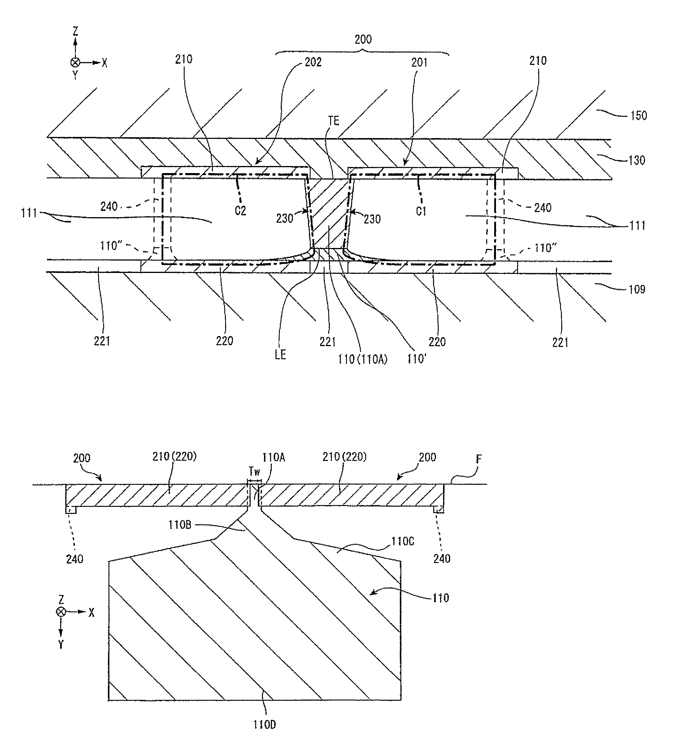
[0037]In the following, the present invention will be explained with reference to the drawings. In each drawing, X, Y, and Z directions are defined by the track width direction, the height direction, and the laminating direction (thickness direction) of layers constituting a perpendicular magnetic recording head, respectively.

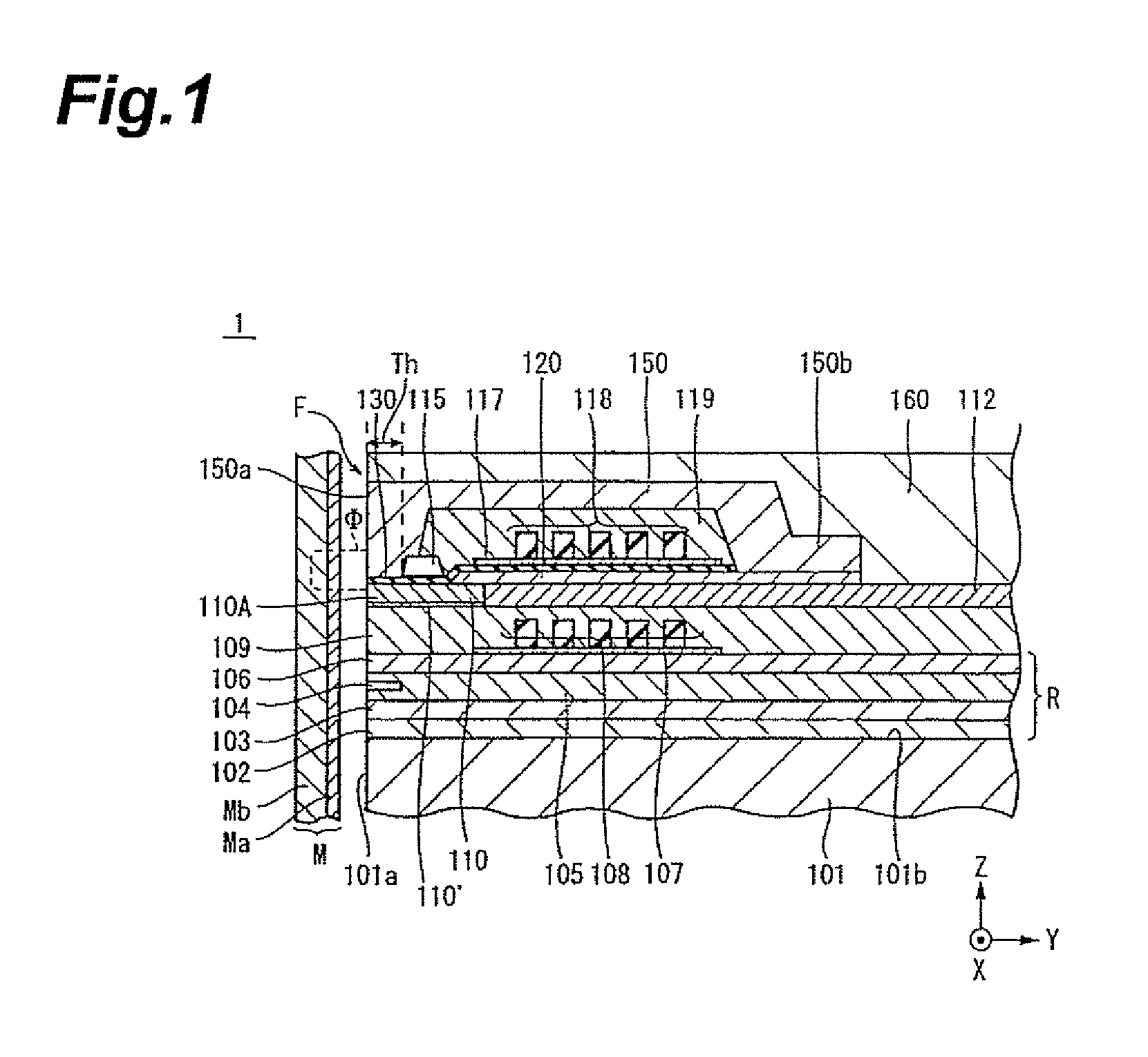
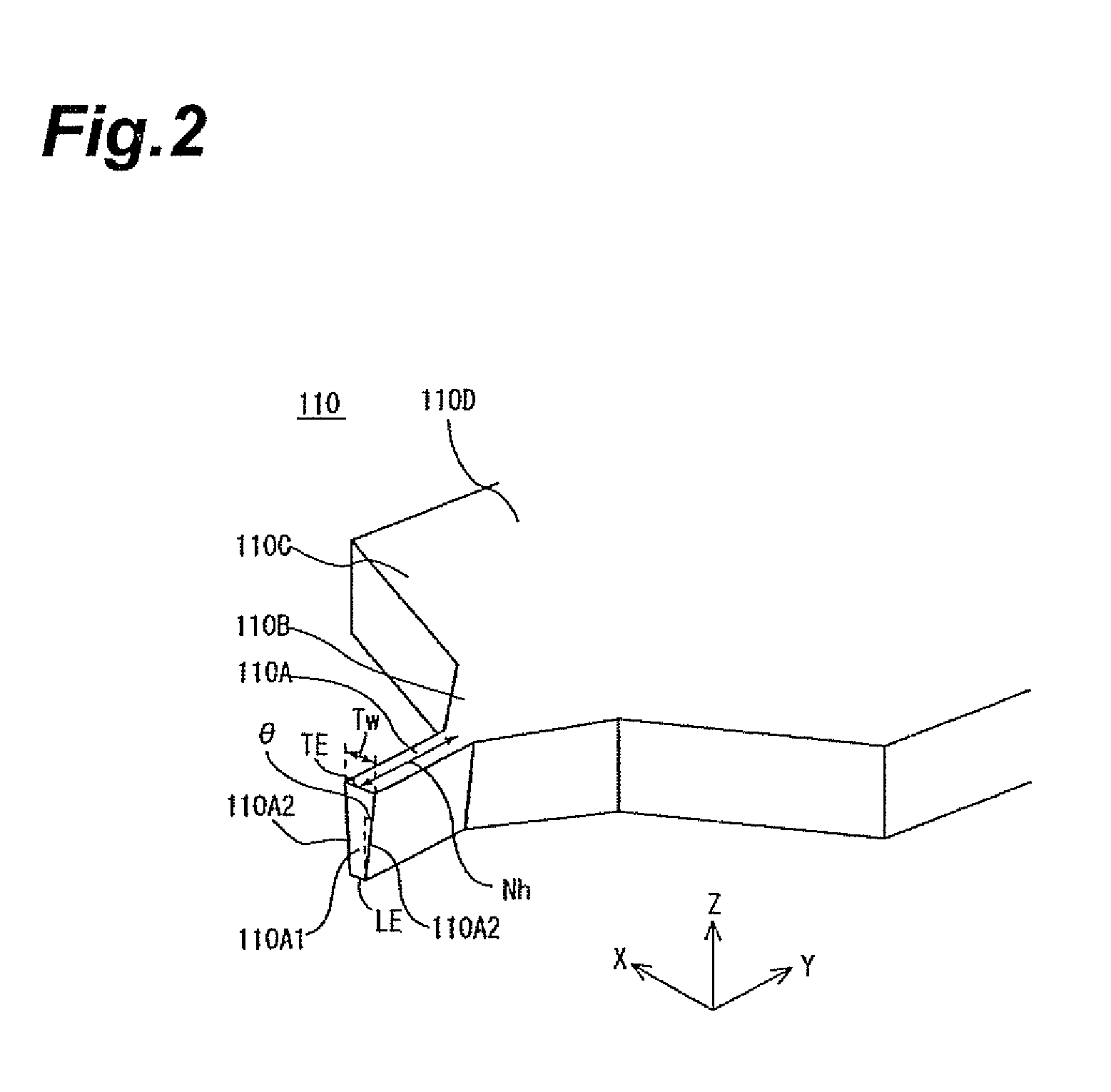
[0038]FIGS. 1 to 10 show the perpendicular magnetic recording head 1 in accordance with a first embodiment of the present invention. FIG. 1 is a vertical sectional view showing the overall structure of the perpendicular magnetic recording head 1, while FIG. 2 is a perspective view for explaining the main magnetic pole form.

[0039]The perpendicular magnetic recording head 1 provides a recording medium M with a recording magnetic flux Φ perpendicular thereto, thereby perpendicularly magnetizing a hard magnetic film Ma of the recording medium M. The recording medium M has the hard magnetic film Ma with a higher remanent magnetization on the medium surface side and ...


PUM

PropertyMeasurementUnit
thicknessaaaaaaaaaa
thicknessaaaaaaaaaa
thicknessaaaaaaaaaa

Abstract

In a perpendicular magnetic recording head having a main magnetic pole layer and a return yoke layer which are laminated with a magnetic gap layer interposed therebetween on a medium-opposing surface, a pair of side coils constituting respective electrically closed circuits on a surface parallel to the medium-opposing surface are provided on both sides in a track width direction of a magnetic pole part of the main magnetic pole layer. When a leakage magnetic field spreading from the magnetic pole part of the main magnetic pole layer passes through the pair of side coils, the pair of side coils generate a demagnetizing field in such a direction as to cancel a magnetic flux change thereof, thereby preventing the leakage magnetic flux from spreading.

Description

BACKGROUND OF THE INVENTION[0001]1. Field of the Invention[0002]The present invention relates to a perpendicular magnetic recording head which performs a recording action by applying a recording magnetic field perpendicularly to a recording medium plane.[0003]2. Related Background Art[0004]As is well-known, a perpendicular magnetic recording head includes a main magnetic pole layer and a return yoke layer which are laminated with a predetermined distance therebetween on a surface opposing a recording medium and are magnetically coupled to each other on the deeper side of the medium-opposing surface in the height direction, a magnetic gap layer interposed between the main magnetic pole layer and return yoke layer on the medium-opposing surface, and a coil layer inducing a recording magnetic field between the main magnetic pole layer and return yoke layer upon energization. The recording magnetic field induced between the main magnetic pole layer and return yoke layer perpendicularly ...

Claims


Application Information

Patent Timeline
Patent Type & Authority Patents(United States)
IPC IPC(8): G11B5/127G11B5/17
CPCG11B5/1278G11B5/3123G11B5/3133
Inventor YAMASHITA, TOMOHIRO
Owner TDK CORPARATION
Why Eureka
Try Eureka