System and method for buffering data received from a network

a network and data buffering technology, applied in the field of communication systems, can solve problems such as problems such as the inability to achieve a suitable transmission rate of data communicated from the transmitting unit to the receiving unit or unit, and achieve the effect of increasing the network throughpu

Inactive Publication Date: 2008-11-13
WALLS JEFFREY JOEL +1
View PDF20 Cites 15 Cited by
  • Summary
  • Abstract
  • Description
  • Claims
  • Application Information

AI Technical Summary

Problems solved by technology

Unfortunately, achieving a suitable transmission rate for the data communicated from the transmitting unit to the receiving unit or units can sometimes be problematic, particularly in instances where a large number of receiving units are to receive the graphical data.

Method used


Image

  • System and method for buffering data received from a network
  • System and method for buffering data received from a network
  • System and method for buffering data received from a network

Examples


Embodiment Construction

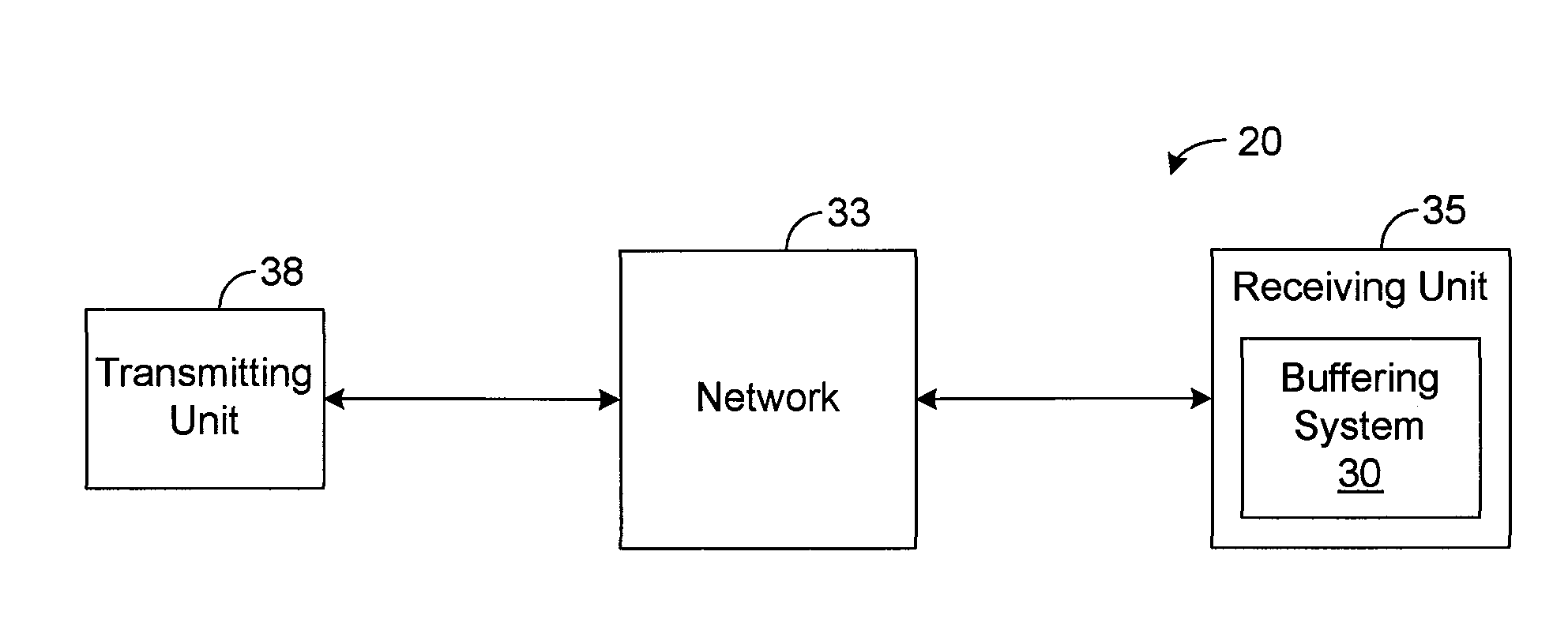
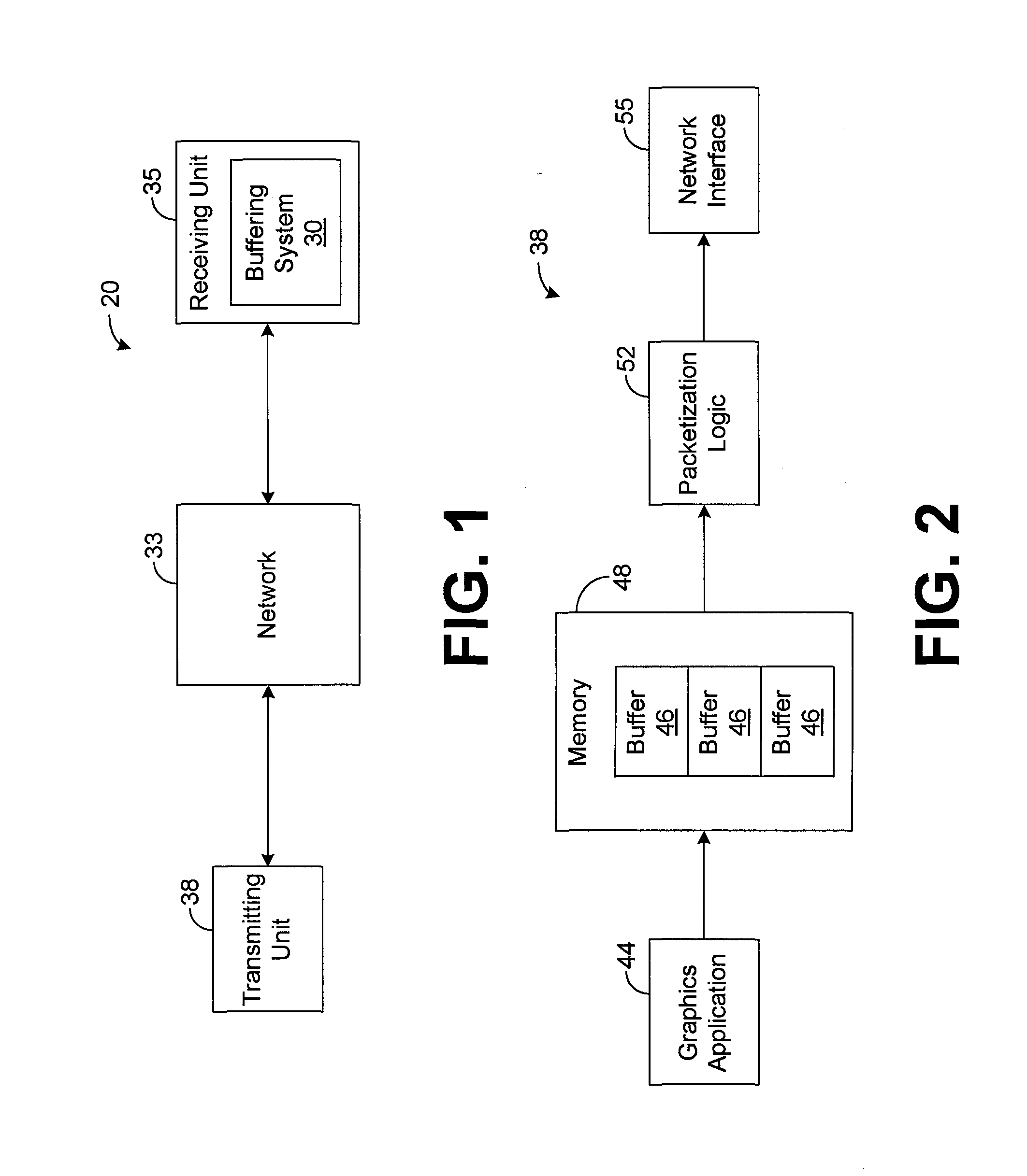
[0018]The present invention generally pertains to a system and method for efficiently buffering data packets. Indeed, FIG. 1 depicts a communication system 20 that employs a buffering system 30 in accordance with an exemplary embodiment of the present invention in order to buffer data packets that are received from a network 33. As shown by FIG. 1, the buffering system 30 resides within a receiving unit 35 that is communicatively coupled to the network 33, and a transmitting unit 38 is configured to transmit at least one sequence of data packets through the network 33 to the receiving unit 35. The buffering system 30 is then configured to temporarily buffer the received data packets before various processing is performed on the data packets by the receiving unit 35 or by various components (not specifically shown) further downstream of the receiving unit 35.

[0019]For illustrative purposes, the system 20 will be described hereafter as communicating graphical data from the transmittin...


PUM


Abstract

A system for buffering data received from a network comprises a network socket, a plurality of buffers, a buffer pointer pool, receive logic, and packet delivery logic. The buffer pointer pool has a plurality of entries respectively pointing to the buffers. The receive logic is configured to pull an entry from the pool and to perform a bulk read of the network socket. The entry points to one of the buffers, and the receive logic is further configured to store data from the bulk read to the one buffer based on the entry. The packet delivery logic is configured to read, based on the entry, the one buffer and to locate a missing packet sequence in response to a determination, by the packet delivery logic, that the one buffer is storing an incomplete packet sequence. The packet delivery logic is further configured to form a complete packet sequence based on the incomplete packet sequence and the missing packet sequence.

Description

CROSS REFERENCE TO RELATED APPLICATION[0001]This application is a divisional of U.S. patent application Ser. No. 10 / 361,742, entitled “System and Method for Buffering Data Received from a Network,” and filed on Feb. 8, 2003, which is incorporated herein by reference.RELATED ART[0002]In some communication systems, such as networked graphical rendering systems, for example, large amounts of data are transmitted from a transmitting unit through a network to at least one receiving unit. For example, a graphics application at a transmitting unit may transmit graphical data to at least one remote receiving unit that renders the graphical data to form a rendered image. In such a system, communication of large amounts of graphical data at a relatively high transmission rate may be needed in order to provide a suitable frame rate for the rendered image.[0003]Performance of a system's transmitting and receiving units in transmitting data to and receiving data from a network is typically an im...

Claims


Application Information

Patent Timeline
Patent Type & Authority Applications(United States)
IPC IPC(8): H04L12/56G06F5/06
CPCG06F5/06G06F2205/064H04L49/90H04L49/901H04L49/9021H04L49/9047
Inventor WALLS, JEFFREY JOELHAMILTON, MICHAEL T.
Owner WALLS JEFFREY JOEL
Why Eureka
Try Eureka