Balloon catheters and methods for treating paranasal sinuses

Active Publication Date: 2008-11-13
ACCLARENT INC
View PDF53 Cites 15 Cited by
  • Summary
  • Abstract
  • Description
  • Claims
  • Application Information

AI Technical Summary

Benefits of technology

[0021] Another method of the invention removes a sinus and cures sinus disease without damage to the surrounding structures such as the optic nerve, extraocular muscles, orbit, brain, meninges, and nasolacrimal duct. The methods of the invention are useful for opening a sinu

Problems solved by technology

An obstruction of the narrow ducts and ostia between the paranasal sinuses and nasal cavity develops, resulting in a vicious cycle of increased secretions, edema, and ultimately organized connective tissue and mucosal hyperplasia.
However some patients become resistant to medical treatment and surgery becomes necessary.
However, endoscopic sinus surgery requires the excision of large areas of bone and nasal mucosa and has reported complications of blindness from damage to the optic nerve, dou

Method used


Image

  • Balloon catheters and methods for treating paranasal sinuses
  • Balloon catheters and methods for treating paranasal sinuses
  • Balloon catheters and methods for treating paranasal sinuses

Examples


first embodiment

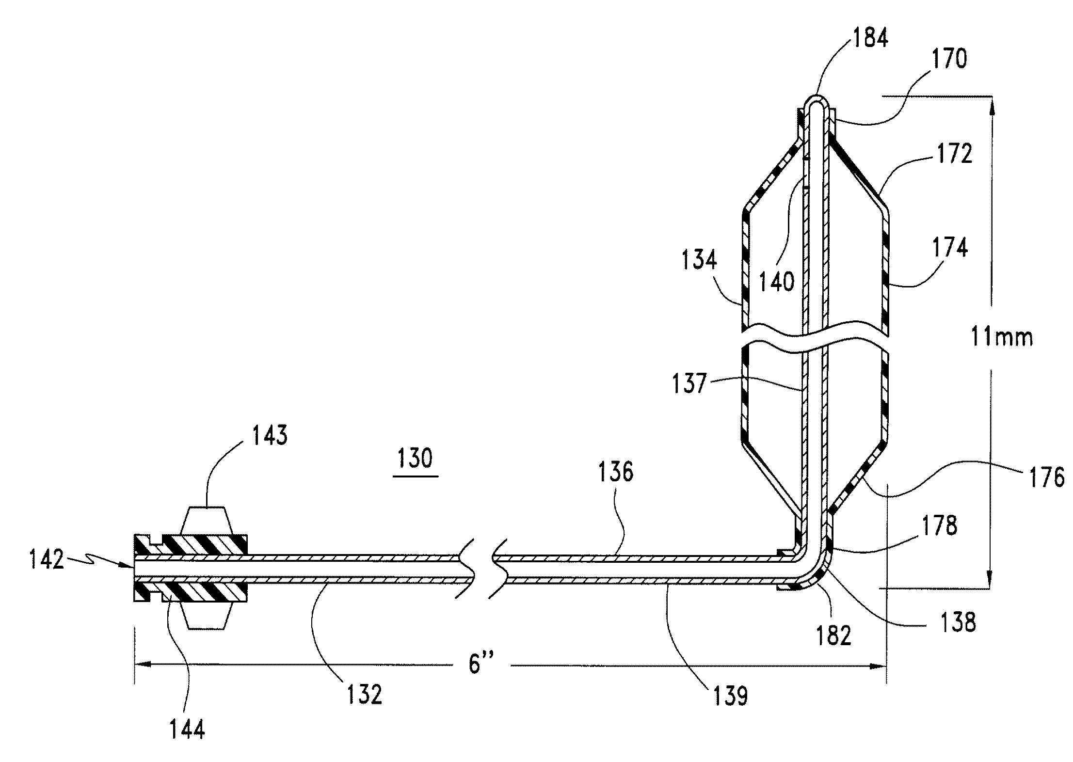
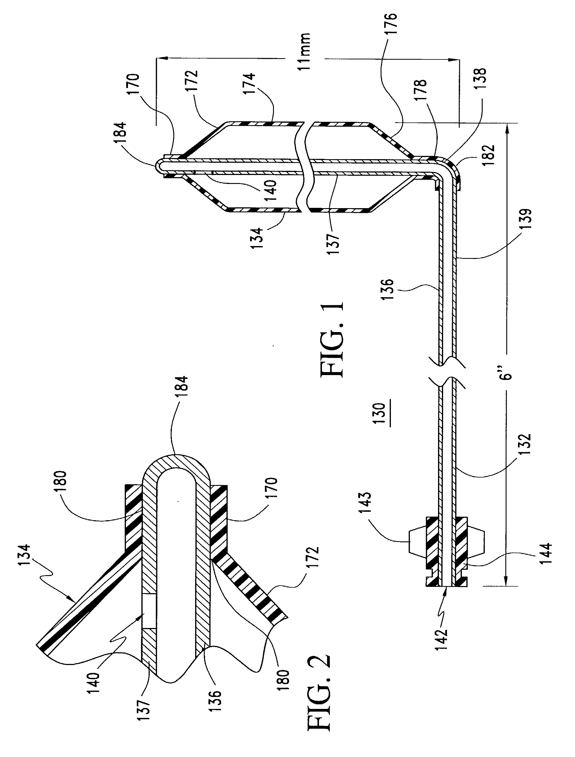
[0040] As shown in FIGS. 1 and 2, a sinus balloon catheter 130 of the invention is assembled from a tube 136, preferably a stainless steel hard tempered hypotube which has a circular bend 138 of 0.13″ radius such that distal segment 137 is oriented 70.degree. to 115.degree., preferably 90.degree., to proximal segment 139. A slot 140 is provided in segment 137. The distance from the distal tip 184 of distal segment 137 to the outer wall of proximal segment 139 of hypotube 136 is 4 mm to 30 mm, preferably 14 mm, as shown in FIG. 1. The distal tip 184 of the hypotube 136 is closed, whereas the proximal end 142 is open. However, the lumen of tube 136 may be closed in distal segment 137, up to 10 mm from distal tip 184, allowing distal tip 184 to remain open. In either case, tube 136 is closed distally of slot 140. The proximal end 142 of hypotube 136 is inserted into a mold for forming luer 144 and plastic is injected into the mold to form luer 144 attached to the end of proximal segmen...

second embodiment

[0043] sinus catheter of the invention is shown in FIG. 3. The catheter 230 is assembled from a tube 236, formed of stainless steel hard tempered hypotube which is straight or has a mild circular bend distally such that distal segment 237 is oriented 130 to 180, preferably 180 degrees, to a long proximal segment 239. The distance from the distal tip 284 of distal segment 237 to the outer wall of proximal segment 239 of hypotube 236 is 10 to 100 mm, preferably 16 mm. The distal tip 284 of the hypotube 236 preferably is closed whereas the proximal end 242 is open. However, the lumen of tube 236 may be closed 0 to 10 mm from distal tip 284 allowing distal tip 284 to be open. The proximal end 242 of hypotube 236 is inserted into a mold for forming luer 244. Heated plastic is injected into the mold to form luer 244 attached to the end of proximal segment 239. The inner diameter of luer 244 matches the external diameter of hypotube 236. The luer 244 has wings 243 or expansions on it to en...


PUM


Abstract

A set of sinus balloon catheters are provided for treating a patient's paranasal sinus system, including dilating prepared openings, and natural ostia and ducts and excising sinus cavities. These include a balloon catheter with a bend placing a distal segment at 90.degree. to a proximal segment and a balloon catheter which is substantially straight. The catheters have sufficient stiffness and column strength that the balloon carrying distal segment of the catheter can be pushed into the prepared opening, natural ostium or duct, or sinus to be excised. The catheters have appropriate inflated working diameters and appropriate outer diameters with the balloon deflated that will enable the catheter to be pushed into the respective prepared opening, natural ostium or duct, or sinus cavity to be excised. The methods use the balloon catheters to dilate prepared openings to selected parts of the sinus system, to dilate natural ostia and ducts of the sinus system, and/or to dilate sinus cavities to remove them.

Description

[0001] This is a divisional of U.S. patent application Ser. No. 10 / 259,300, filed Sep. 30, 2002.FIELD OF THE INVENTION [0002] This invention relates to balloon catheters and methods using such catheters for treating paranasal sinuses. BACKGROUND [0003] To fully understand the invention, it is necessary to consider the anatomy and physiology of the sinus system. FIGS. 4-16, which show various steps of methods of the invention, also show important features of sinus anatomy. The maxillary sinus 21 lies lateral to the nasal cavity 38, inferior to the eye orbit 23 and superior to the palate or roof of the mouth. The medial wall of the maxillary sinus forms the lateral nasal wall 44 inferiorly. The frontal sinus 35 (FIG. 16) lies above the orbit and its floor is formed by the frontal bone and is contiguous with part of the orbital roof. The right and left frontal sinuses are divided by the interfrontal septum. The frontal sinus drains into the nasal cavity and its outflow tract is in the ...

Claims


Application Information

Patent Timeline
IPC IPC(8): A61M29/00A61F2/958A61M29/02
CPCA61M25/10A61M2210/0681A61M2210/0618A61M29/02A61B17/32A61M25/1002A61M25/10181
Inventor BECKER, BRUCE
Owner ACCLARENT INC
Why Eureka
Try Eureka