Clutch for insulated glass window covering

a technology of insulated glass and window covering, applied in the field of window coverings, to achieve the effect of reducing the amount of operator effor

Inactive Publication Date: 2008-11-20
ODL
View PDF16 Cites 32 Cited by
  • Summary
  • Abstract
  • Description
  • Claims
  • Application Information

AI Technical Summary

Benefits of technology

[0007]The aforementioned problems are overcome in the present invention in which an IG blind assembly includes a clutch bearing to variably add friction to an IG internal blind or covering assembly. When the clutch is inactive the bearing is free-rolling which allows the blind pull cords to move freely around the bearing and reduce the amount of operator effort needed to raise the blinds. When the

Problems solved by technology

Upon raising the blinds, the clutch rotates as the cord passes over; and upon

Method used


Image

  • Clutch for insulated glass window covering
  • Clutch for insulated glass window covering
  • Clutch for insulated glass window covering

Examples


Embodiment Construction

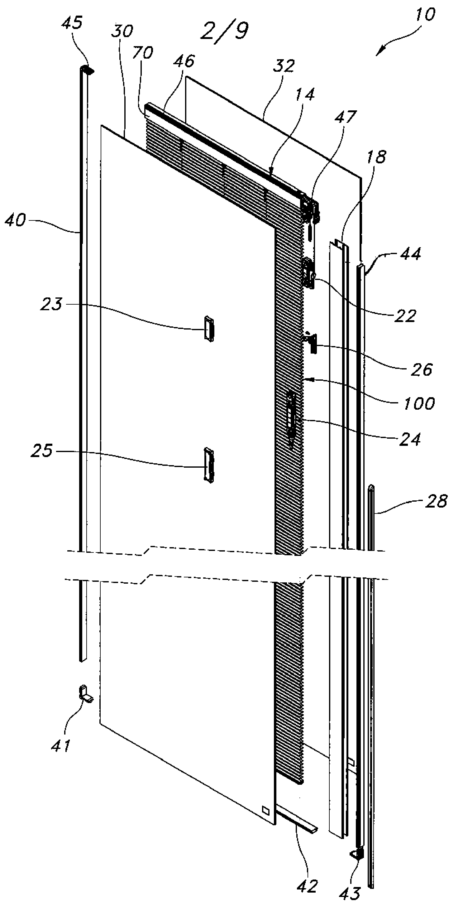
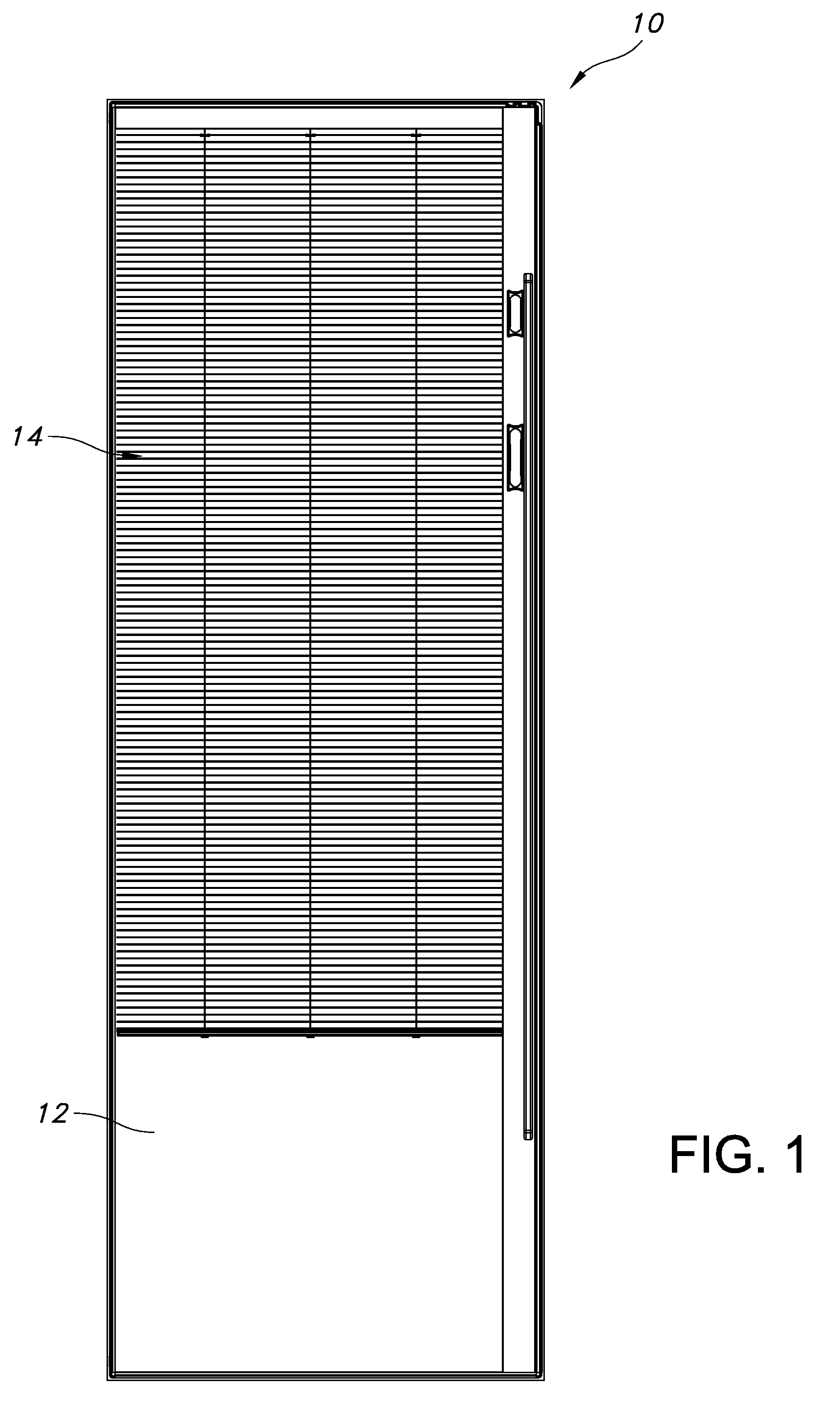
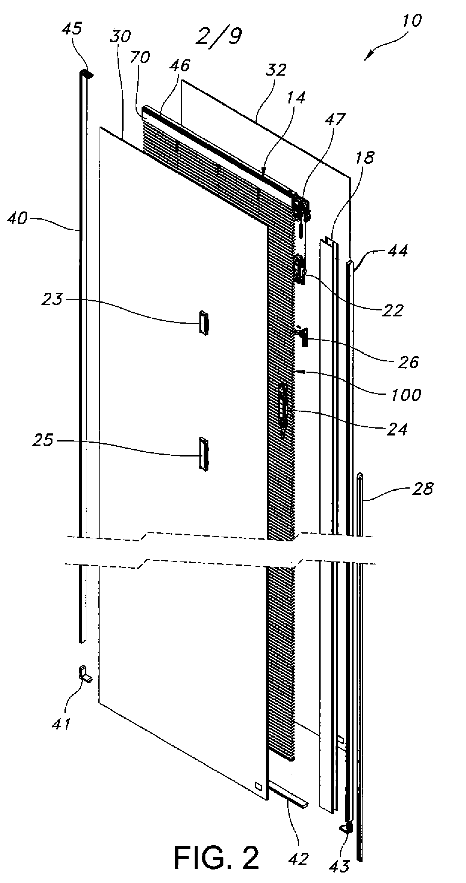
[0029]An IG blind assembly with a clutch bearing is illustrated in the figures and generally designated 10. In the current embodiment, two in-line clutch bearing assemblies 80, 82 are integrated into one of the corner key assemblies 47. Blind pull cords 13 are attached at one end to the blinds 50 and routed through the clutch bearing assemblies 80, 82, through the follower 24 and attached to the intermediate pulley 26. As operator 25 is lowered, the follower 24 also lowers, pulling the blind pull cords 13 in the direction of the follower 24 through the free-rolling clutch bearing assemblies 80, 82, ultimately raising the blinds 50. As operator 25 is raised the follower 24 also raises, pulling the blind pull cords 13 in the the direction of the blinds 50 through the locked clutch bearing assemblies 80, 82, ultimately lowering the blinds 50. This is merely one embodiment of the invention, a person of ordinary skill in the art would understand how to implement alternative clutch and bl...


PUM


Abstract

An insulated glass (IG) internal blind assembly including a clutch for providing directional friction when raising and lowering the blind. The clutch is directionally activated, the gravitational pull of the blinds or lowering the blinds activates the clutch causing it to lock and add friction to the system. The clutch may be placed essentially anywhere along the cord path where the path changes direction. Various clutch and cord configurations may be used to achieve a desired amount of directional friction. The directional friction prevents the window covering from falling under its own weight.

Description

BACKGROUND OF THE INVENTION[0001]The present invention relates to window coverings, and more particularly to window coverings contained within insulated glass.[0002]Insulated glass window assemblies with internal window coverings are well known. The insulated glass includes two spaced glass panels sealed to a spacer frame to define a space between the panels. A window covering, such as a blind or shade, is positioned within the space and is operable using operators on the outside of the insulated glass that are magnetically coupled through the glass to the blind assembly. An example of such a construction is illustrated in U.S. Pat. No. 6,932,139 filed Aug. 6, 2003 by Early et al, the disclosure of which is incorporated by reference.[0003]In one implementation of an IG internal blind assembly, the blinds are raised and lowered using an external operator that is magnetically coupled to an internal follower. One end of a blind pull cord attaches to the follower and the other end attac...

Claims


Application Information

Patent Timeline
IPC IPC(8): E06B9/264
CPCE06B9/264E06B2009/2646
Inventor HUMMEL, BENJAMIN P.OUZTS, ALLEN C.CORNISH, JOSHUA R.
Owner ODL
Why Eureka
Try Eureka