
Folding chair

a folding chair and seat technology, applied in the field of folding chairs, can solve the problems of lack of appropriate solutions, poor quality of the type 1 chair, and inability to meet the requirements of contract quality standards, and achieve the effect of increasing the bottom weigh

Active Publication Date: 2008-11-20
MAYERCHECK ROBERT P
View PDF19 Cites 14 Cited by
  • Summary
  • Abstract
  • Description
  • Claims
  • Application Information

AI Technical Summary

Benefits of technology

[0010]For this use, a lightweight chair that could be easily carried by each participant from an indoor office to the outside deck is desired. It also could be conveniently stored within the office and not in a central storage location, so that it can be readily used when desired. For client entertainment needs the chair preferably is special and comfortable and not left out in the elements.
[0026]In yet another embodiment, the back, front and rear leg posts are constructed of wood and can be attached to modified joints, back and leg stringers. In this design, the stringers can be cast aluminum for greater bottom weight. This added weight may be partially offset with back and seat designs that are made of perforated lightweight composites. This approach can be used in windy outdoor conditions to help prevent tip-over of the lightweight chair.

Problems solved by technology

The chairs of Type 1, 2, and 3 can satisfy a wide range of business needs, but in certain environments, an appropriate solution is lacking.
Type 1 chairs are somewhat heavy and cumbersome to carry, especially with one hand.
They are not typically used in a contract office setting and are not manufactured to contract quality standards.
They are commonly used in training or conference settings and can be quite uncomfortable.
Type 2 and 3 chairs are comfortable, but rather heavy, and not conveniently stored and carried from an office to a deck, especially if it is up a short flight of stairs, or separated by door rails.

Method used


Image

  • Folding chair
  • Folding chair
  • Folding chair

Examples


Embodiment Construction

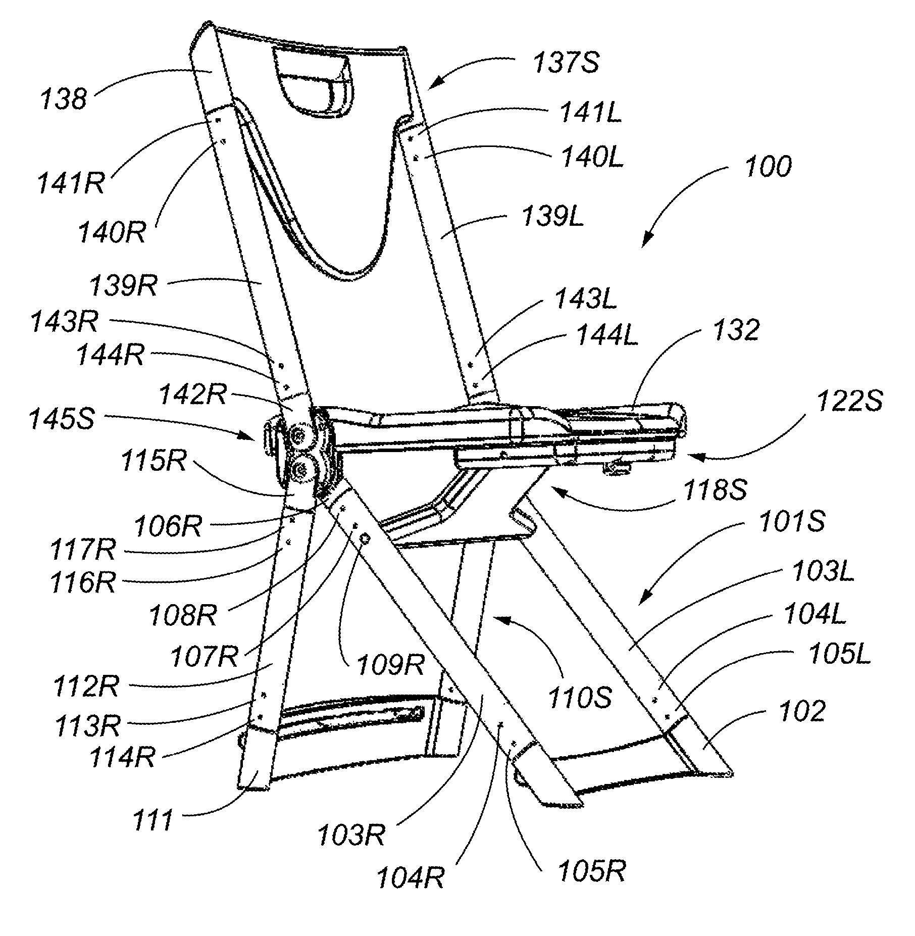
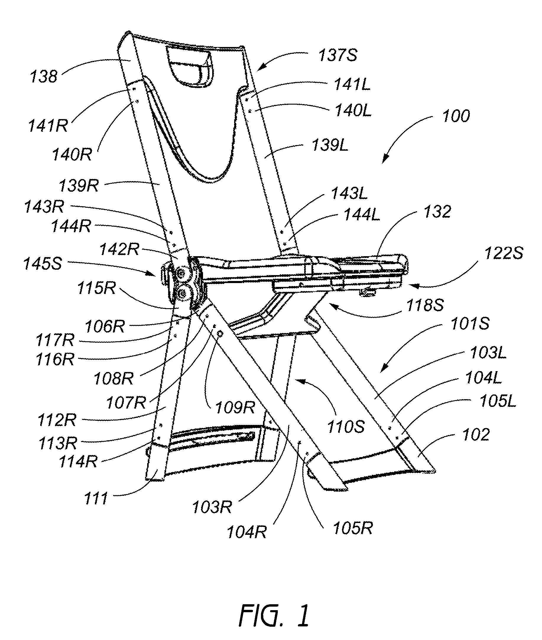
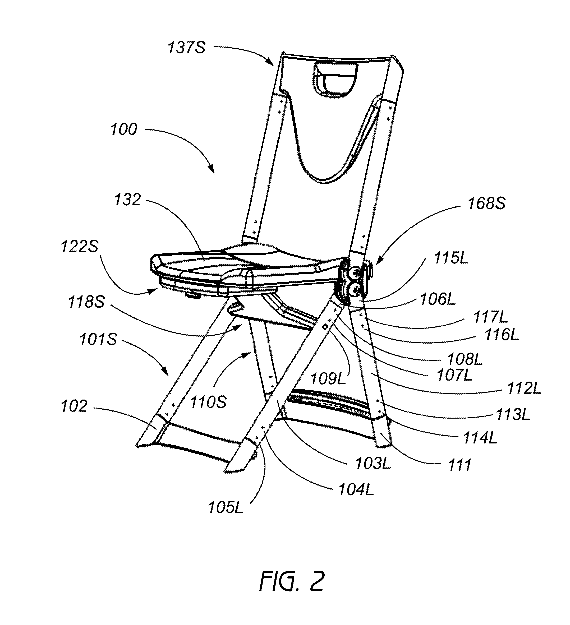
[0051]Reference will now be made to the drawings wherein like numerals refer to like parts throughout. FIGS. 1-5 illustrate an embodiment of an open folding chair assembly 100 that is arranged and configured in accordance with certain features, aspects and advantages of the present invention. In some embodiments, the open folding chair assembly 100 comprises a seat 132 to which is attached a right gearbox subassembly 145S in a manner described below. The right gearbox subassembly 145S preferably is on the right side of the folding chair as defined by a user while sitting in the folding chair 100. In FIG. 2, a left gearbox subassembly 168S also is shown attached to the seat 132 on the left side in a manner similar to the right gearbox subassembly 145S. The gearbox subassemblies 145S, 168S control the folding motion of the chair 100 during opening and closing and are described in more detail below.

[0052]In the illustrated configuration, a front leg subassembly 101S is fastened to the ...


PUM


Abstract

A folding chair utilizes a gear train to control a folding motion and to achieve a compact closed form. While holding a handle integrated into a backrest, the weight of the chair allows it to open and unfold automatically into an open position. The folding chair locks in place in the open position. To refold the chair, a button is depressed to release the lock and the seat is pulled toward the backrest. The gear train refolds the front and rear legs. In the compact folded position, the lightweight chair can be carried with one hand in a relaxed position, similar to an attache case. The handle is contoured so that it is possible for an adult to carry two chairs back to back in each hand.

Description

CROSS-REFERENCE TO RELATED APPLICATIONS[0001]This application claims the priority benefit under 35 U.S.C. §119(e) of U.S. Provisional Patent Application No. 60 / 938877, filed on May 18, 2007, which is incorporated by reference in its entirety.BACKGROUND OF THE INVENTION[0002]1. Field of the Invention[0003]The present invention generally relates to folding chairs and in particular to a chair that folds compactly in a controlled fashion.[0004]2. Description of the Related Art[0005]Chairs presently used in business environments for occasional use are available in several types of configurations. These configurations are chiefly known by the nature of how the chairs are efficiently stored when not in use.[0006]In the past, one type of chair (type 1) could fold by having the front and rear legs compress together along with the seat. The back is formed as part of the front legs that extend upward. An example of this type of design is illustrated by a chair disclosed in U.S. Pat. No. 6,871,...

Claims


Application Information

Patent Timeline
Patent Type & Authority Applications(United States)
IPC IPC(8): A47C4/04
CPCA47C4/14A47C4/10
Inventor MAYERCHECK, ROBERT P.
Owner MAYERCHECK ROBERT P
Learn More