Inkjet printing apparatus and inkjet printing method

a printing apparatus and inkjet technology, applied in the direction of printing, other printing apparatus, etc., can solve the problems of image defects, printing mediums that are likely to be placed in unstable conditions, and the accuracy of printing mediums is likely to be reduced, so as to reduce density unevenness and reduce distance

Inactive Publication Date: 2008-11-20
CANON KK
View PDF5 Cites 11 Cited by
  • Summary
  • Abstract
  • Description
  • Claims
  • Application Information

AI Technical Summary

Benefits of technology

[0016]An object of the present invention is to reduce density unevenness which takes place due to a sudden error in conveyance of a printing medium in a configuration of conveying the printing medium at a decreased distance while the printing medium is being held by only either an upstream conveying unit or a downstream conveying unit. Particularly, the present invention is preferably applied to an inkjet printing apparatus and an inkjet printing method of making a printing by use of multiple inks which are different in color tone from one another.

Problems solved by technology

In addition to these types of image defects stemming from the reduced accuracy with which a printing medium is conveyed, another type of image defect stems from a printing medium which is not held by both the upstream conveying unit and the downstream conveying unit.
As a result, the printing medium is likely to be placed in an unstable condition.
This causes image defects, including a white stripe, a black stripe and a granular impression.
However, a uniform reduction of the one-time conveying distance throughout the printing medium reduces printing throughput.
If, however, the front and rear end portions thereof are conveyed at a shorter distance at one time than the central portion thereof while a range of nozzles within a nozzle arrangement range of the printing head is used to perform the printing without any change, the density becomes uneven because there is a difference in the number of printing scans in a unit of printing area between the front and rear end portions of the printing medium, and the central portion thereof.
However, the inventors of the present invention have found that a mere application of the techniques disclosed in the foregoing documents rather performs the printing density uneven in some cases.
In some cases, an error in conveyance of a printing medium suddenly takes place due to an impact which occurs when the front end of the printing medium goes into the downstream conveying unit (or plunges into a nipping part between the discharge roller and the spur rollers).
In addition, in some cases, another error in conveyance of the printing medium suddenly takes place due to an impact which occurs when the rear end of the printing medium comes out of the upstream conveying unit (or is released from the nipping part between the conveying roller and the pinch rollers).
This brings about a problem that the sudden conveyance error varies density or brightness obviously.

Method used


Image

  • Inkjet printing apparatus and inkjet printing method
  • Inkjet printing apparatus and inkjet printing method
  • Inkjet printing apparatus and inkjet printing method

Examples


first embodiment

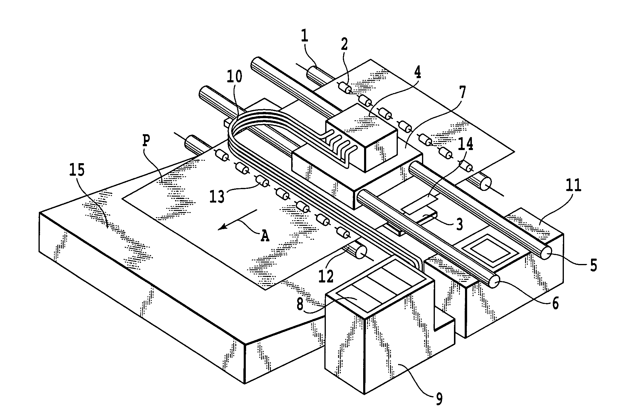
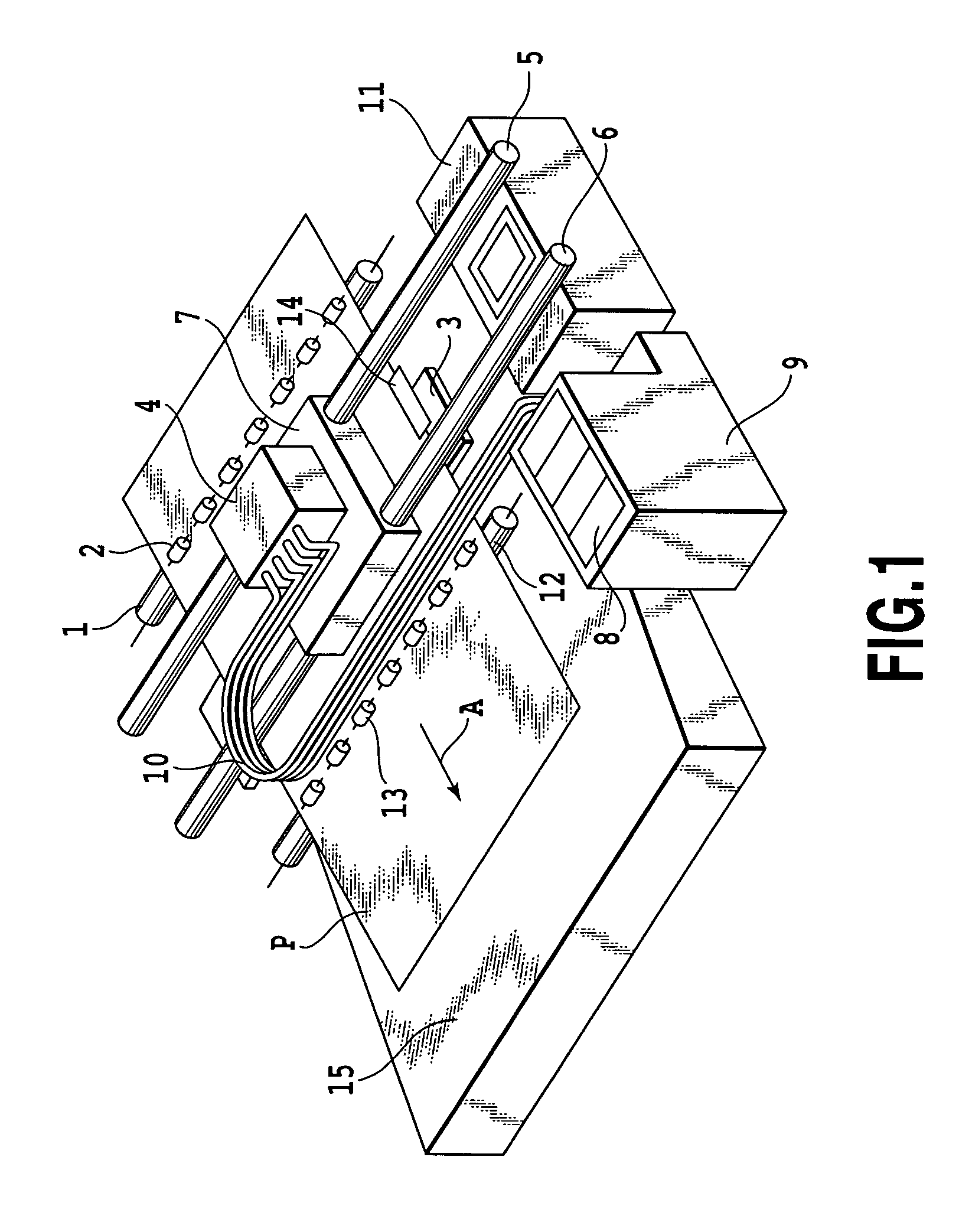
[0059]FIG. 1 is a perspective view showing an overall configuration of an inkjet printing apparatus according to one of the embodiment of the present invention. While a printing is performed, a printing medium P is held between a conveying roller 1 arranged on a conveying path and pinch rollers 2 driven by the conveying roller 1, and is conveyed in a direction indicated by an arrow A in FIG. 1 while guided onto and supported by a platen 3 in response to the rotation of the conveying roller 1. The pinch rollers 2 are elastically biased toward the conveying roller 1 by a pressing member such as a spring, which is not illustrated in FIG. 1. The conveying roller 1 and the pinch rollers 2 are components constituting a first conveying unit located upstream in a direction in which the printing medium is conveyed.

[0060]The platen 3 is placed in a printing position which is opposed to a face (or an ejection face) of an inkjet-head typed printing head 4 where ejection openings are formed. The...

second embodiment

[0108]FIGS. 19A, 19B and 19C are diagrams each showing a configuration of nozzle arrays in a printing head adopted for a second embodiment of the present invention, and concurrently each used for explaining how the nozzles are used for the central portion, the transitional portions, as well as the front and rear end portions. The printing head according to the present embodiment includes nozzle array 41Gy for the grey (Gy) ink in addition to nozzle arrays 41C for the cyan ink, nozzle array 41M for the magenta ink, nozzle array 41Y for the yellow ink, and nozzle array 41Bk for the black ink. The number of nozzles in each nozzle array, a density with which the nozzles are arranged in the printing head, and the grouping of the nozzles in the printing head are the same as those in the first embodiment. A numeric value in each block representing each group indicates a print allowing rate of the group. Hatched nozzle groups (or groups whose print allowing rate is not equal to 0 (zero)) be...

third embodiment

[0113]Each of the foregoing embodiments shifts the position of the nozzle-use range in the nozzle array for the specific (or black) ink from the positions of the nozzle-use ranges in the nozzle arrays for the other color inks (or the chromatic color inks), and makes the size of the nozzle-use range for the black ink different from the size of the nozzle-use ranges for the chromatic color inks, when these nozzle-use ranges are used for each of the transitional portions. However, the present invention shall not be limited to the foregoing embodiments if there is another embodiment which is capable making the position of the peak of the brightness variation different among each colors in transitional portion by expanding the width of the overall brightness variation, and accordingly of reducing the absolute value of a value obtained by combining the peak values of the brightness variations concerning the respective colors as well.

[0114]FIGS. 22A, 22B and 22C are diagrams each showing a...


PUM


Abstract

Provided is an inkjet printing apparatus for performing a printing with a first nozzle array for ejecting a first color ink and a second nozzle array for ejecting a second color ink. The apparatus reduces density unevenness stemming from a sudden error in conveyance of a printing medium. When the apparatus performs a scan with respect to the printing medium for printing in which using ranges of nozzles in the first and second nozzle arrays are restricted to parts thereof, the restricted using ranges of the first and second nozzle arrays are shifted from each other. Thereby, the density unevenness stemming from the error in conveyance occur in positions which are different between the first and second colors, Thus, it possible to make the overall density unevenness less obvious by making gradients of variations in brightness and chroma of an image smaller.

Description

BACKGROUND OF THE INVENTION[0001]1. Field of the Invention[0002]The present invention relates to an inkjet printing apparatus and an inkjet printing method. Specifically, the present invention relates to a technique for suppressing an image defect attributed to an error in conveyance of a printing medium.[0003]2. Description of the Related Art[0004]A general configuration of an inkjet printing apparatus includes a conveying unit for conveying a printing medium along a predetermined conveying path, and a printing head in which nozzles are arranged for ejecting the inks on the printing medium thus conveyed. The inkjet printing apparatus performs a printing by an alternate series of an operation for ejecting the inks from the nozzle while causing the printing head to move in the main scanning direction different from a direction in which the nozzles are arranged and an operation for causing the conveying unit to convey the printing medium in a sub-scanning direction orthogonal to the m...

Claims


Application Information

Patent Timeline
Patent Type & Authority Applications(United States)
IPC IPC(8): B41J29/38
CPCB41J2/2132B41J11/0065B41J13/0027
Inventor KANO, YUTAKATAJIKA, HIROSHI
Owner CANON KK
Why Eureka
Try Eureka