Antenna Selection Apparatus and Methods

a technology of antenna selection and apparatus, applied in the field of wireless communications, can solve the problems of existing schemes subject to deterioration in performance, circuitry consumes additional power, and the implementation and design costs of building this additional circuitry

Inactive Publication Date: 2008-11-20
THE GOVERNORS OF THE UNIV OF ALBERTA
View PDF21 Cites 15 Cited by
  • Summary
  • Abstract
  • Description
  • Claims
  • Application Information

AI Technical Summary

Problems solved by technology

As a result, there are implementation and design costs associated with building this additional circuitry.
Furthermore, in normal operation, this circuitry consumes additional power, which can be problematic for limited-power applications such as i

Method used


Image

  • Antenna Selection Apparatus and Methods
  • Antenna Selection Apparatus and Methods
  • Antenna Selection Apparatus and Methods

Examples


Embodiment Construction

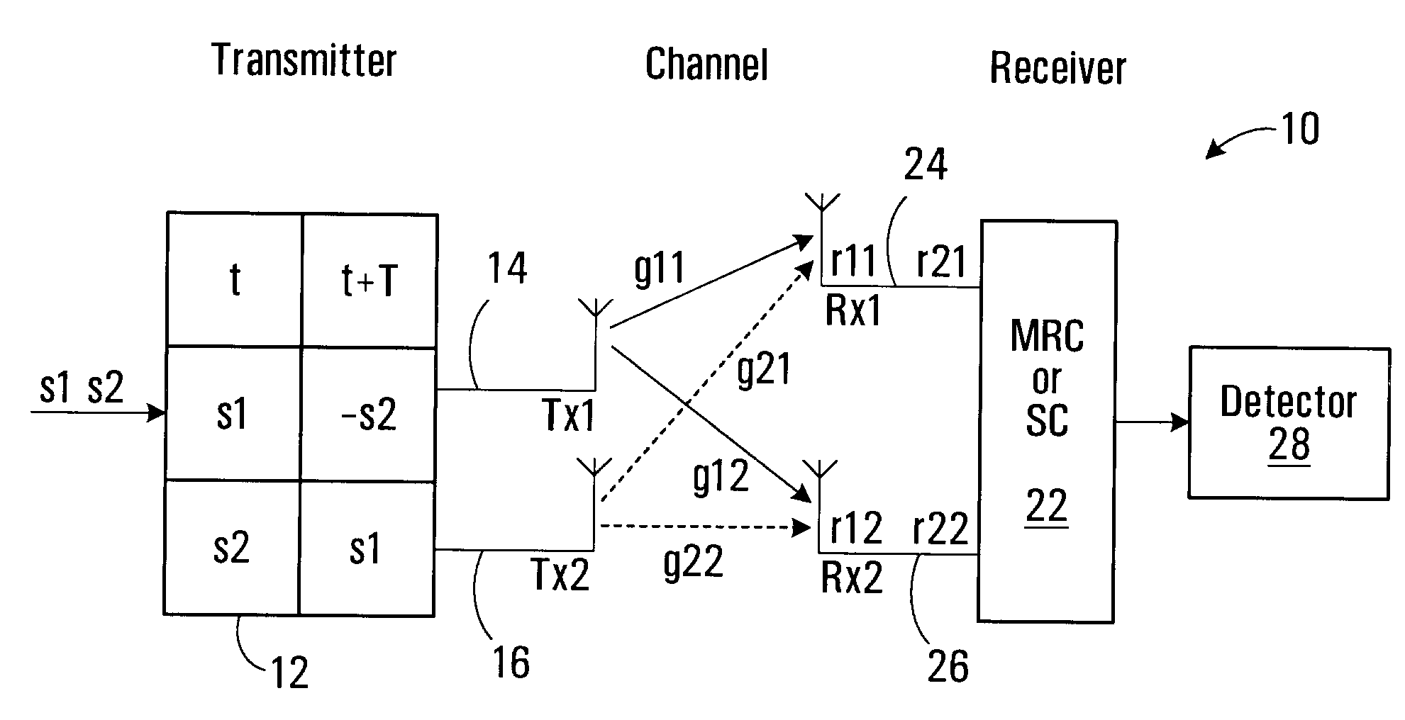
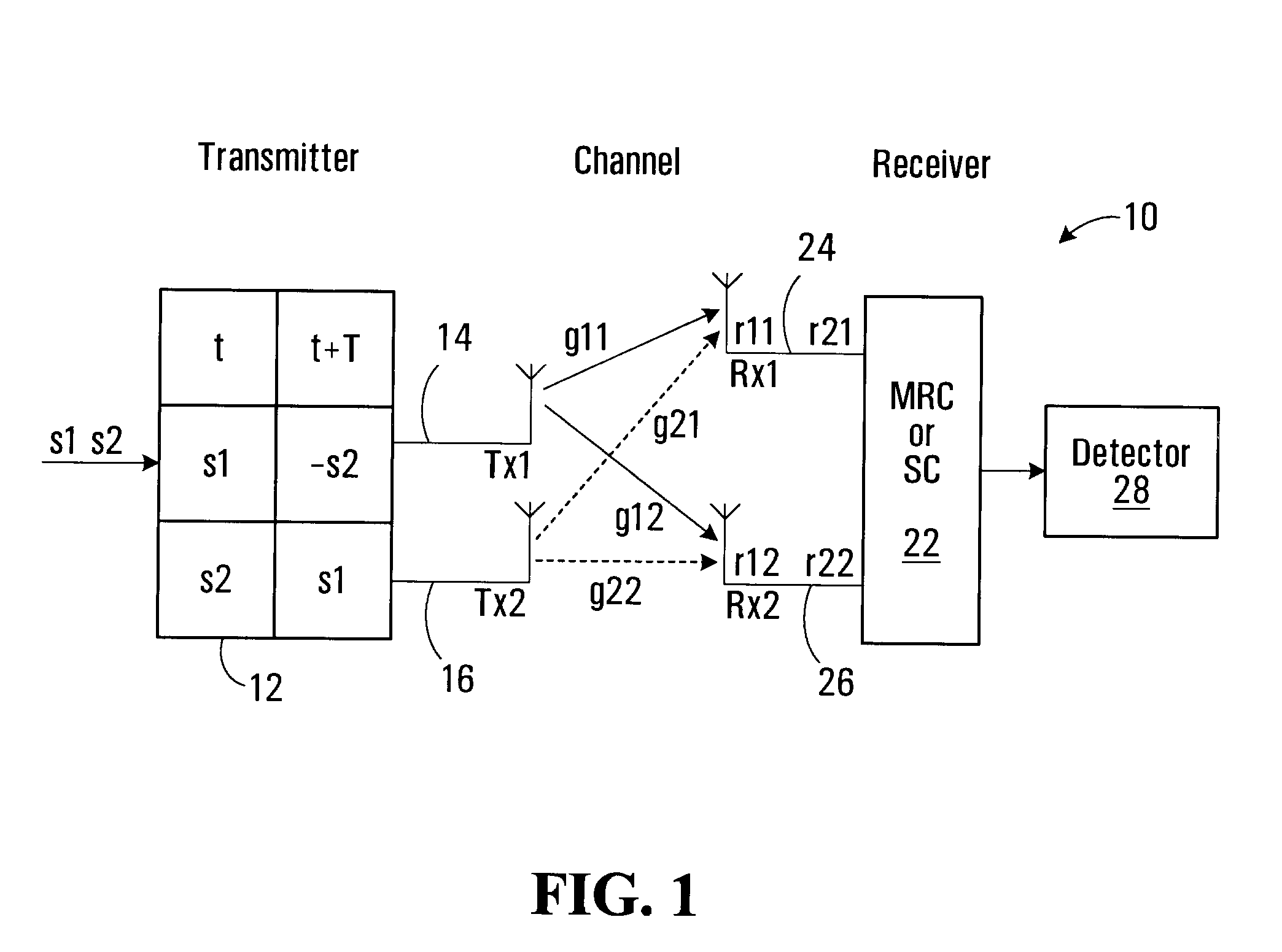
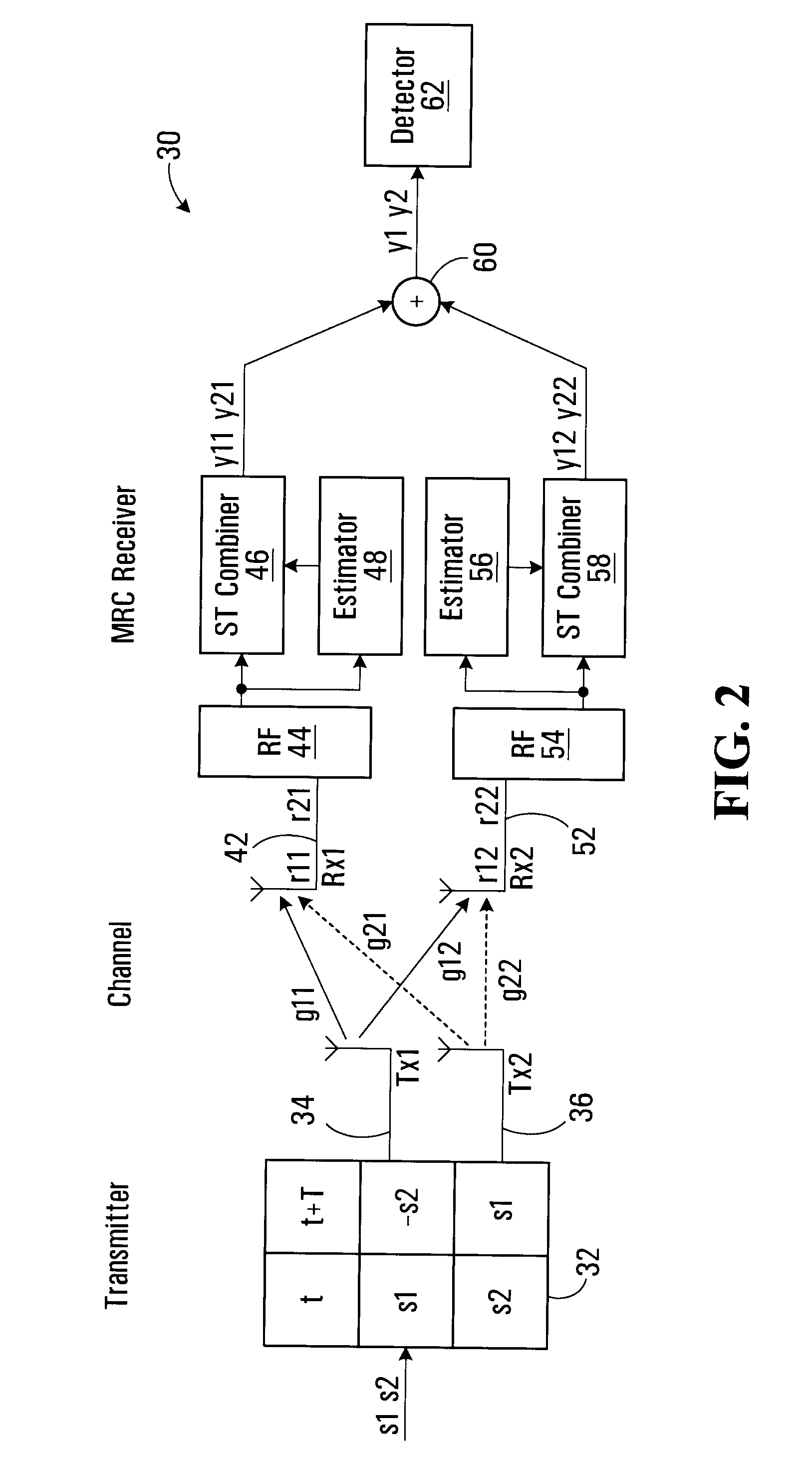
[0034]Multiple-input multiple-output (MIMO) systems have attracted great interest since they can improve the capacity and reliability of wireless communication channels. The benefits of a MIMO system are discussed in G. Foschini and M. Gans, “On the limits of wireless communications in a fading environment when using multiple antennas,”Wireless Personal Commun., vol. 6, no. 3, pp. 311-335, March 1998, which is hereby incorporated by reference in its entirety. However, adopting a MIMO system increases the system complexity and the cost of implementation. A promising approach for reducing implementation complexity and power consumption, while retaining a reasonably good performance, is to employ some form of antenna selection.

[0035]In general, MIMO antenna selection combining (SC) includes receiver (Rx) antenna selection, transmitter (Tx) antenna selection and joint Tx / Rx selection. Both Tx / Rx selection and Tx selection require channel estimation to be fed back from the receiver to th...


PUM


Abstract

An apparatus and method for antenna selection diversity are provided. Antennas are selected by summing moments of space-time block encoded signals received via each respective antenna and selecting at least one antenna with the largest moment sum.

Description

RELATED APPLICATION[0001]The present application is related to and claims the benefit of U.S. Provisional Application No. 60 / 703,418, filed Jul. 29, 2005, entitled “ANTENNA SELECTION APPARATUS AND METHODS”, which is hereby incorporated by reference in its entirety.FIELD OF THE INVENTION[0002]This invention relates generally to wireless communications and, in particular, to antenna selection.BACKGROUND[0003]The Alamouti scheme is an important wireless transmitter diversity technique. It is part of the 3G standard (both IEEE 802.16 and IMT 2000), which represents the future of broadband wireless service. With two transmitter antennas, it is proven to provide much better system performance than systems with only one transmitter antenna. The 3G standard uses it to implement the downlink transmission from mobile stations to mobile terminals or the transmission specification for mobile base stations. Thus, mobile terminals, such as mobile phones, wireless PDAs, WiFi computers, etc., must ...

Claims


Application Information

Patent Timeline
IPC IPC(8): H04L27/22
CPCH01Q1/2216H01Q1/241H01Q3/26H04B7/0669H04B7/0857H04B7/0874H04B7/0891
Inventor BEAULIEU, NORMANLI, WENYU
Owner THE GOVERNORS OF THE UNIV OF ALBERTA
Why Eureka
Try Eureka