Biometric Sensor

Inactive Publication Date: 2008-11-20
KONINKLIJKE PHILIPS ELECTRONICS NV
View PDF8 Cites 23 Cited by
  • Summary
  • Abstract
  • Description
  • Claims
  • Application Information

AI Technical Summary

Problems solved by technology

When measuring these signals, some problems have to be overcome.
A first problem relates to the fact that the human skin is a poor conductor.
A penetrating sensor, for instance a needle, penetrates the skin and will have a good electrical contact with the conductive parts of the body below the skin, but such sensors are not suitable in practical situations.
Contact electrodes, in the form of a conductive plate placed in close contact with the skin, suffer from the relatively high contact resistance between the sensor and the skin.
In order to reduce this problem by improving the galvanic contact, wet electrodes are used, comprising a conducting gel (containing silver chloride) between the conductive plate and the skin; however, this gel can cause irritations or even allergic reaction.
However, such capacitive sensors introduce problems of a different kind.
The most important problems in this respect are related to the fact that such capacitive sensors are also sensitive to electrical signals generated by the surroundings.
A second problem relates to comfort for the user.
In such applications, rigid sensors are undesirable, because they are not comfortable for the user.
Further, rigid s

Method used


Image

  • Biometric Sensor
  • Biometric Sensor
  • Biometric Sensor

Examples


Embodiment Construction

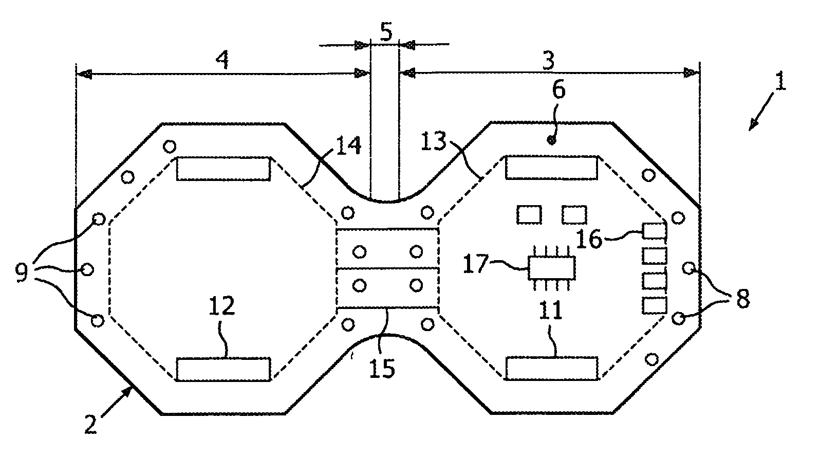
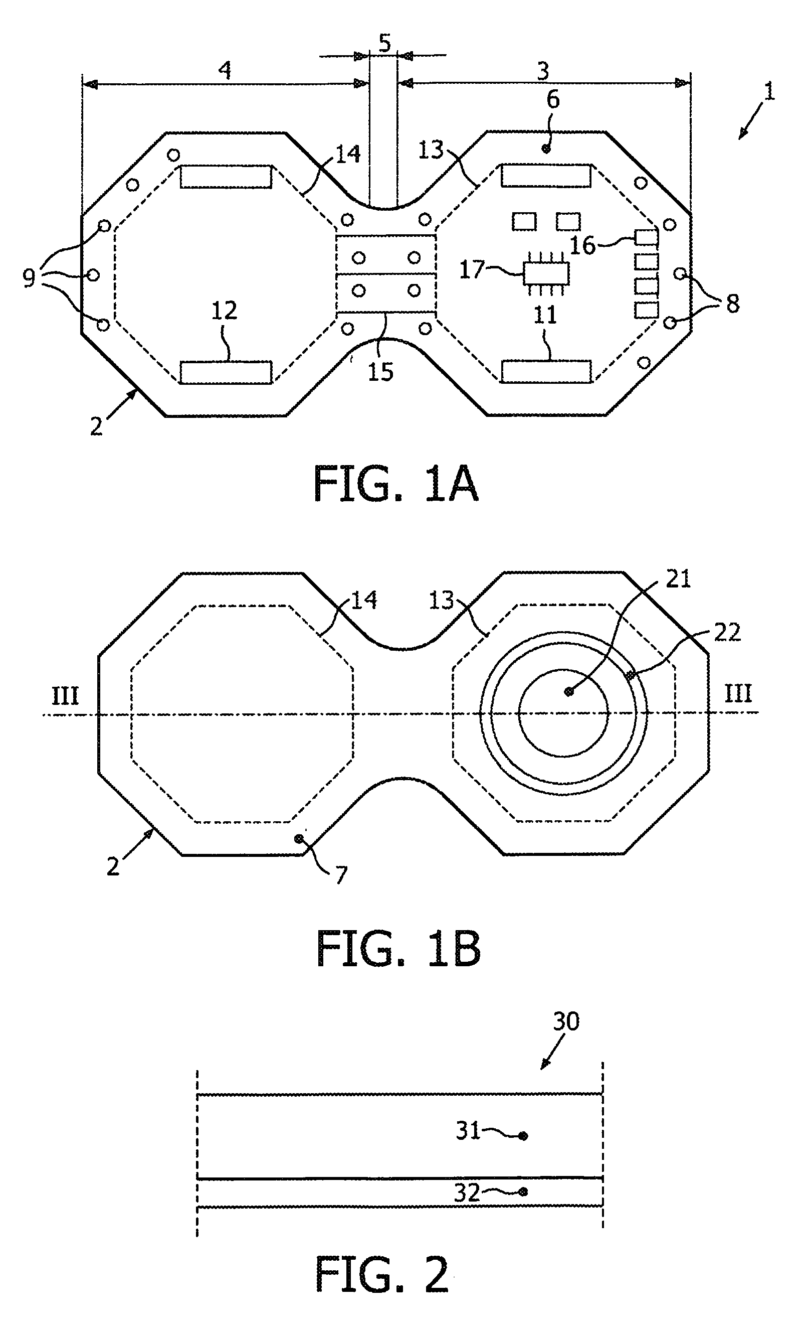
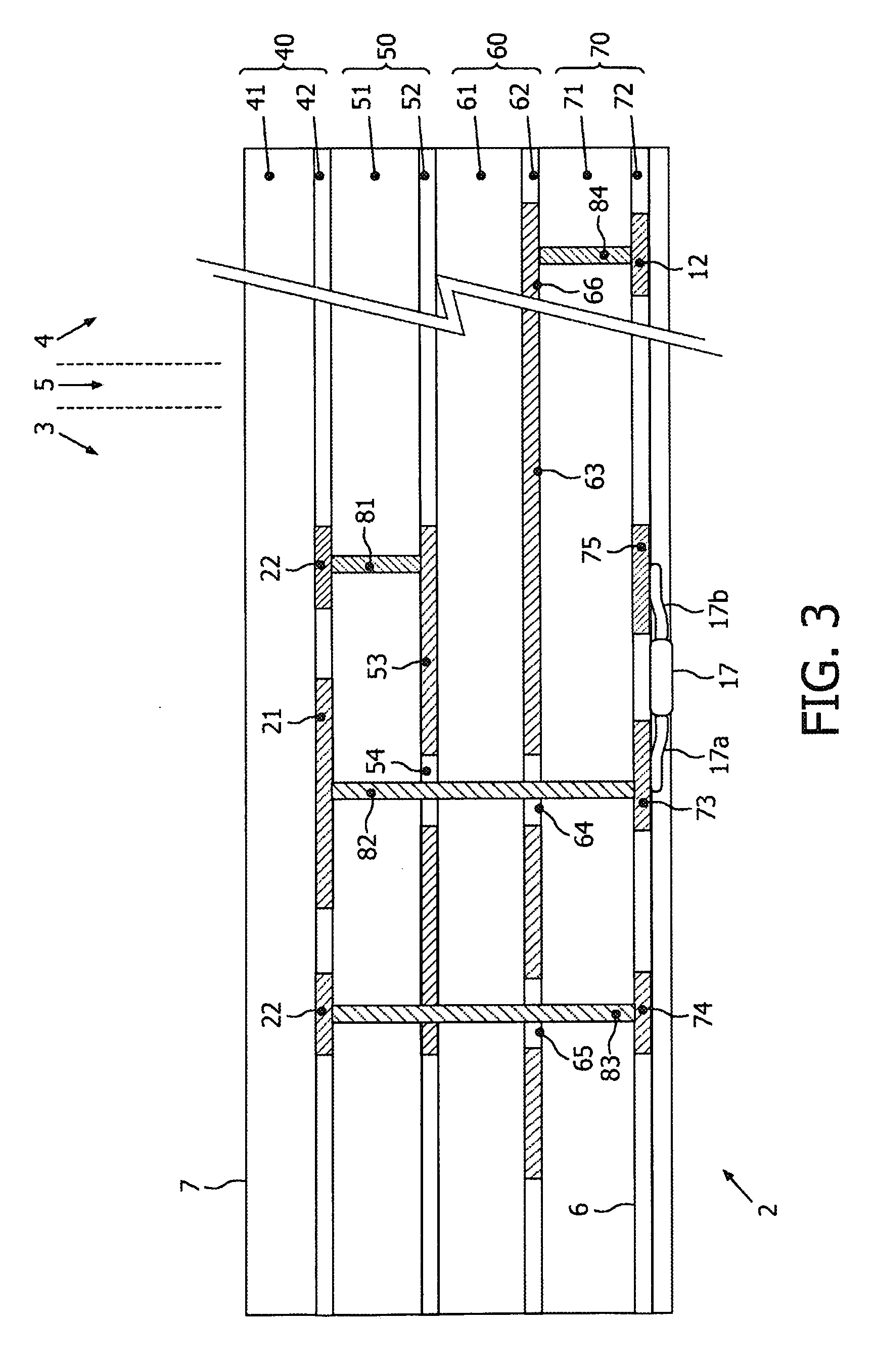
[0019]FIG. 1A is a schematic inside view of a preferred embodiment of a biometric sensor device 1 according to the present invention, and FIG. 1B is a schematic outside view of the same device. The sensor device 1 comprises a thin, flexible sensor body 2, comprising two wing parts 3, 4 attached to each other at a fold portion 5. The sensor body 2 has two opposite main surfaces, i.e. a first main surface 6 visible in the inside view of FIG. 1A, and an opposite second main surface 7, visible in the outside view of FIG. 1B. In use, the two wing parts 3, 4 will be folded together, such that the fold portion 5 takes the shape of a loop, and the first main surfaces 6 of the two wing parts will be facing each other; for this reason, the first main surface 6 will also be indicated as “inside surface”, whereas the opposite second main surface 7, which will be on the outside of the device when folded as mentioned, will also be indicated as “outside surface”.

[0020]The shape of the contour of t...


PUM


Abstract

A bio metric sensor device (1) comprises: —a thin, flexible, layered sensor body (2); —a conductive sense plate (21); —a first non-conductive layer (41) between the sense plate and an outer surface (7); —a conductive shield plate (53) having a passage opening (54), overlaying the sense plate; —a second non-conductive layer (51) between the sense plate and the shield plate; —conductive circuit lines (73) on an inner surface (6); —a non-conductive separation layer (61, 71) between the shield plate and the circuit lines; —a signal processing circuit (100) mounted on the inner surface (6), the circuit (100) comprising a differential amplifier (110) having an input (111); —a conductive interconnector (82) crossing the second non-conductive layer (51) and the separation layer (61, 71), extending through the passage opening (54) of the shield plate (53), coupling the sense plate (21) and said input (111) of said amplifier (110).

Description

FIELD OF THE INVENTION[0001]The present invention relates in general to a biometric sensor for sensing bioelectrical signals.BACKGROUND OF THE INVENTION[0002]It is commonly known that electrical signals are generated on various places of the human body, these signals being representative for electrical activity inside the human body. Important sources of such electrical activity are the heart, the brain, moving muscles, etc. It is already known to measure these electrical signals, and to provide a time-registration of these signals such as for instance an electrocardiogram (ECG), an electro-encephalogram (EEG), an electro-myogram (EMG), in order to obtain information regarding certain body conditions.[0003]When measuring these signals, some problems have to be overcome. A first problem relates to the fact that the human skin is a poor conductor. In this context, measuring sensors can be classified as follows. A penetrating sensor, for instance a needle, penetrates the skin and will ...

Claims


Application Information

Patent Timeline
IPC IPC(8): A61B5/0408
CPCA61B5/0408A61B5/04284A61B5/0478A61B5/411A61B5/7203A61B2562/182A61B5/25A61B5/291A61B5/302
Inventor PASVEER, WILLEM FRANKEOUWERKERK, MARTINOOSTVEEN, JIM T.
Owner KONINKLIJKE PHILIPS ELECTRONICS NV
Why Eureka
Try Eureka