
Plastic identification clip

a technology of identification clip and plastic, applied in the direction of snap fasteners, clothes clips, buckles, etc., can solve the problems of difficult to remember how many yards of fabric were bought, and the fabric that was bough

Inactive Publication Date: 2008-11-27
SOLICH CATHERINE
View PDF3 Cites 12 Cited by
  • Summary
  • Abstract
  • Description
  • Claims
  • Application Information

AI Technical Summary

Benefits of technology

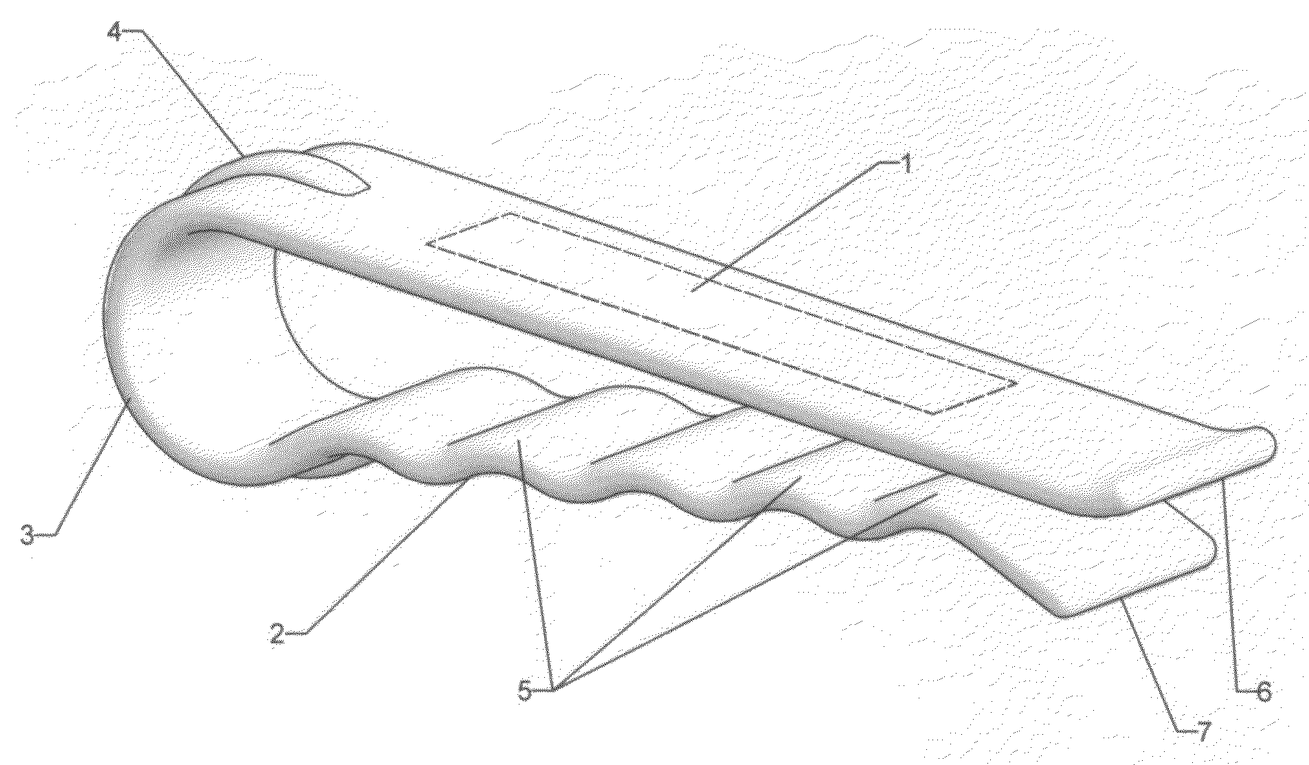
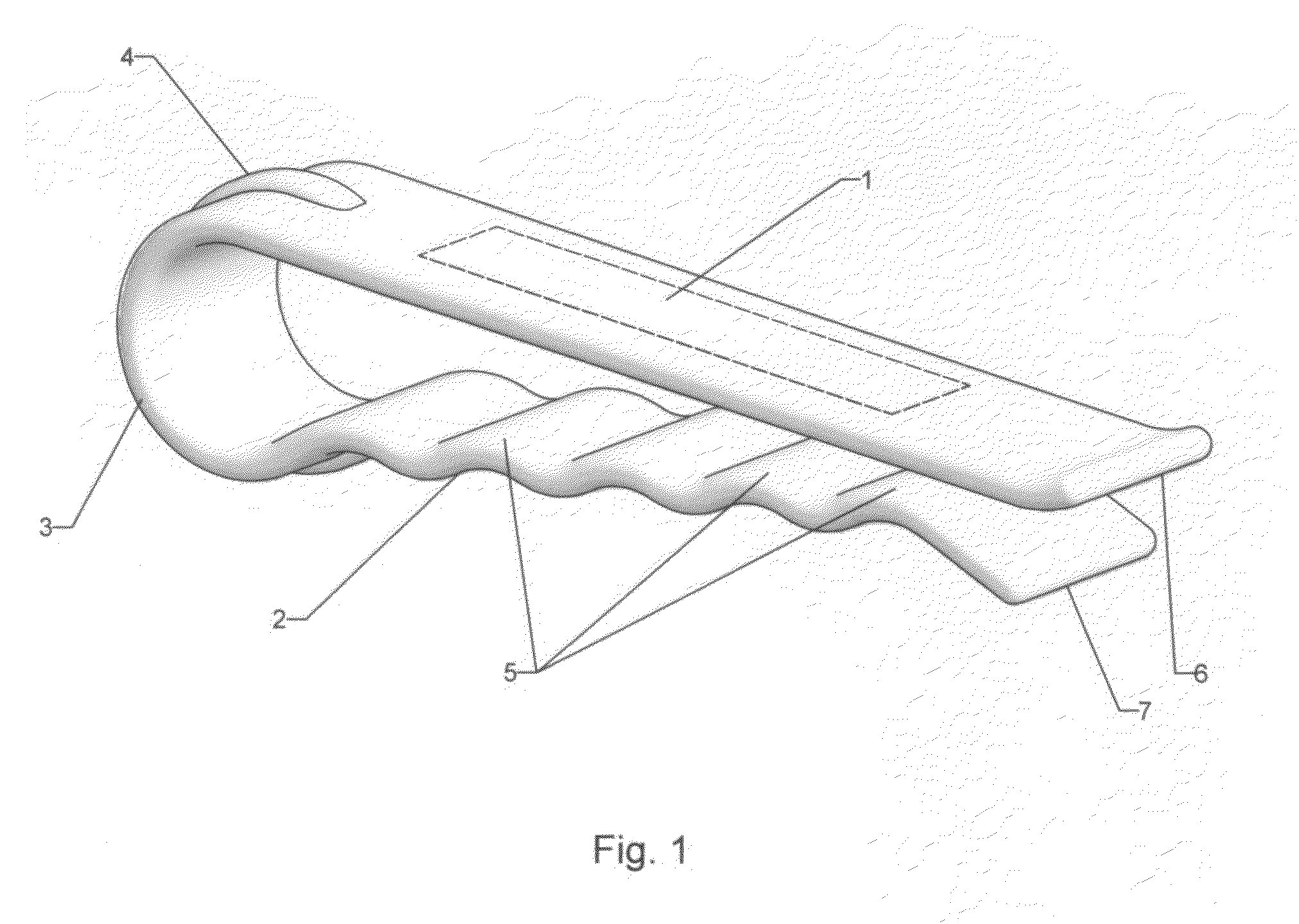
[0012]The inventive concept addresses a very common problem for the average home sewer or quilter. The clip not only helps to identify the number or size and / or numbers or style of garments but could be used to bundle or clamp a stack of fabrics or papers. There is no more pulling out the sheet or table linen from in between a pile and then having to refold the same because it was the size or item or having to take the time to remeasure. The fabric that was bought “on sale” months ago or how many yards were bought is difficult to remember.The inventive clip is made of a flat plastic strip of material and then is doubled back upon itself to form a U-shaped configuration. One leg of the U-shape remains flat while the other leg is being provided with lateral corrugations to enhance the gripping or friction power of the clip. The U-shape section has a raised welt or bulge thereon on the outside and around the U to add clamping power to the clip when clipped to a heavy stack of materials. The flat leg of the U-shaped clip on its outside surface is a location where identifying notes may placed to identify any desired identifiers thereon such as, Nos. of yards, square or round, knitted or woven or use of the item. The front end of the U-shape should be slightly spread apart to aid in placing the clip on heavy stacks. In addition, the ends should be slightly turned upwardly, again, to enhance the motion of applying the clip to a stack.

Problems solved by technology

The fabric that was bought “on sale” months ago or how many yards were bought is difficult to remember.

Method used


Image

  • Plastic identification clip
  • Plastic identification clip

Examples


Embodiment Construction

[0014]FIG. 1 (the only Fig.) shows a perspective view of the inventive clip. This FIG. 1 shows the basic FIG. 1 which clearly shows the two legs 1 and 2 of the U-shaped configuration. One of the legs 1 of the U-shape has a flat surface on its outer surface to be able to write a notation thereon or to apply a decal thereon. The U of the clip is shown at 3. It is also clear from this FIG. 1 that the two legs of the U diverge from each other as they are approaching the U or the turn of the legs. This is done on purpose because it will aid the use of the clip when applied to thin or thick bundles. The thicker bundles will be accommodated in the U end of the clip when thick bundles are to be clamped together.

At the outside surface of the U end of the clip there is provided a linear tensioning or reinforcing welt or bulge 4 which will provide an additional tensioning force when the two legs of the U-shaped clip are spread apart to a more extent.

One leg 2 of the clip has corrugations 5 pro...


PUM


Abstract

The inventive concept is an identification clip that is made of a flat plastic material and formed into a U-shaped form. One of the legs of the U-shape has a flat outer surface to place indicia thereon either in writing or in a decal form. The other leg of the U-shaped form has lateral corrugations thereon to enhance the friction force when the clip is applied to a bundle of materials. Both of the legs of the U-shaped form are diverging from each other toward the U end. This will enlarge the loading capacity of the clip. The U end of the clip has a longitudinal bulge on its outer surface to increase the tensioning of the clip as the clip encounters heavier bundles. The open ends of the both legs of the U have upturned edges thereon to make it easier when applying the clip to any object. That object may be a bundle of fabric folded upon itself in several layers or it may be a stack of fabrics or papers etc.

Description

[0001]This application is a Continuation-In-Part of the provisional application No. 60 / 931,396, filed on May 23, 2007.BACKGROUND OF THE INVENTION[0002]There are may clips used for many projects such as cloths pins, diaper clasps, clip fasteners for garments or hem clips. The following citation are considered the closest prior art:[0003]Des. 235,052 illustrates a unitary clothes pin made in a U-shape having a triangular U as a tension enhancer.[0004]Des. 373,868 discloses a clothes pin having an elongated U-shaped and flat return and having enlarged front ends.[0005]Des. 207,844 illustrates a clip fastened for a garment having a circular back end and open front ends.[0006]Des. 360,053 discloses a hair roller clip that has rearward extensions that are used to open the front and of the clip.[0007]Des. 376,883 shows a clothes pin of a unitary construction having two forward ends that are slightly spaced apart.[0008]Des. 402,778 illustrates a clothes pin that is of a rigid construction h...

Claims


Application Information

Patent Timeline
IPC IPC(8): A44B21/00A44B99/00
CPCA44B99/00Y10T24/44991D06F55/00
Inventor SOLICH, CATHERINE
Owner SOLICH CATHERINE
Learn More