Laminate type battery and method for manufacturing the same

a technology of laminated type and battery, which is applied in the direction of secondary cell servicing/maintenance, cell components, and flat cell grouping, etc., can solve the problems of poor space efficiency and achieve the effect of high space efficiency

Inactive Publication Date: 2008-11-27
NISSAN MOTOR CO LTD
View PDF5 Cites 1 Cited by
  • Summary
  • Abstract
  • Description
  • Claims
  • Application Information

AI Technical Summary

Benefits of technology

[0006]The present invention was made in consideration of the above-described problems. It is an object of the present invention to provide a laminate type battery with high space efficiency and a method for manufacturing the same.

Problems solved by technology

However, this bipolar battery has a construction in which many members are combined together and thus has a problem of poor space efficiency.

Method used


Image

  • Laminate type battery and method for manufacturing the same
  • Laminate type battery and method for manufacturing the same
  • Laminate type battery and method for manufacturing the same

Examples


first embodiment

[0024]The laminate type battery according to the first embodiment will be described hereinbelow with reference to the drawings.

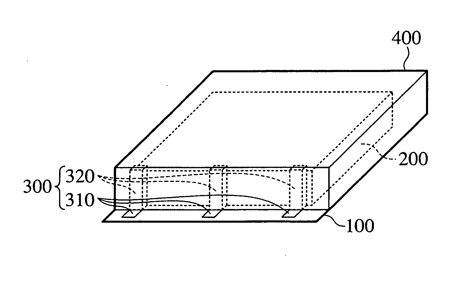
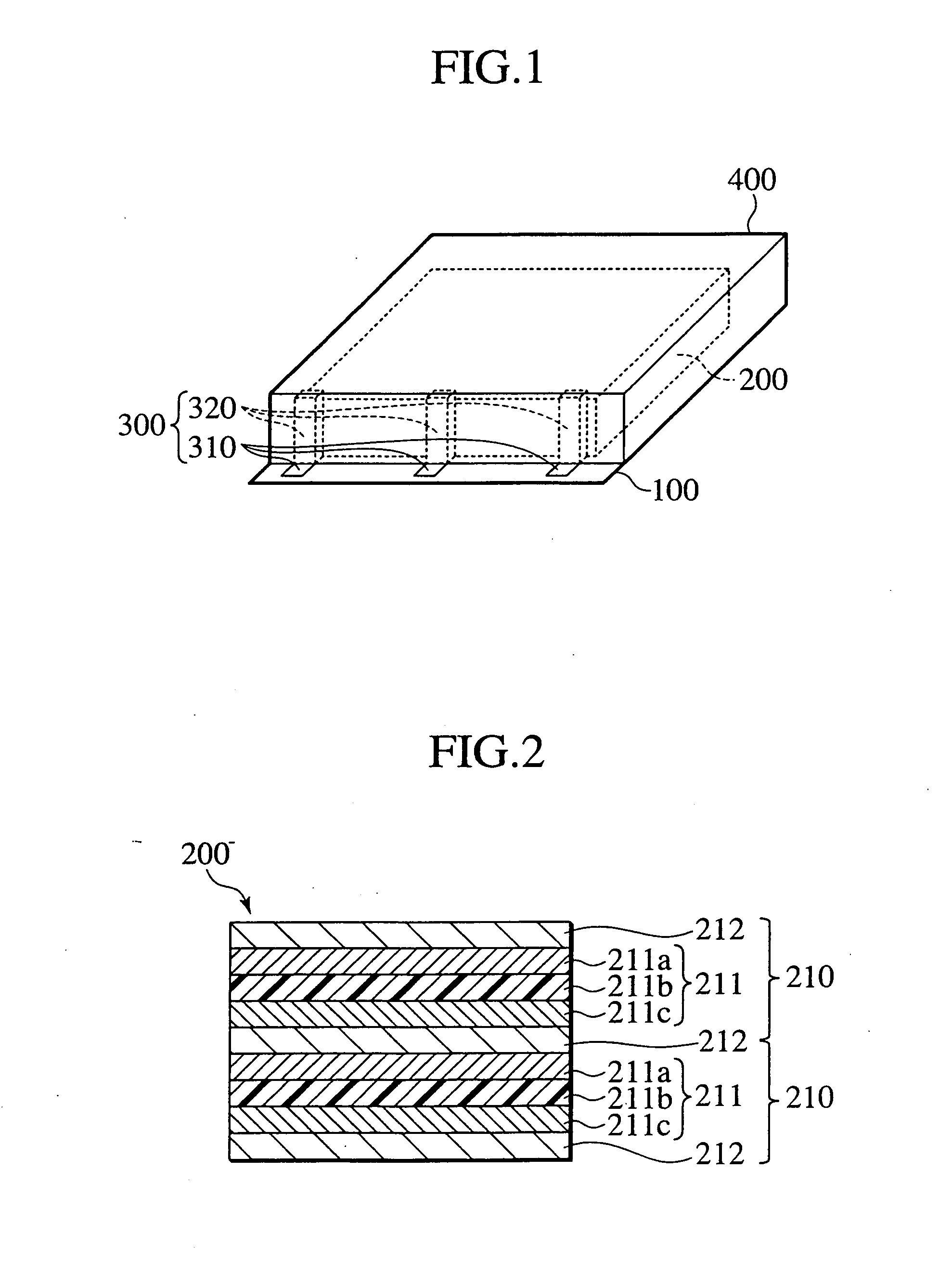
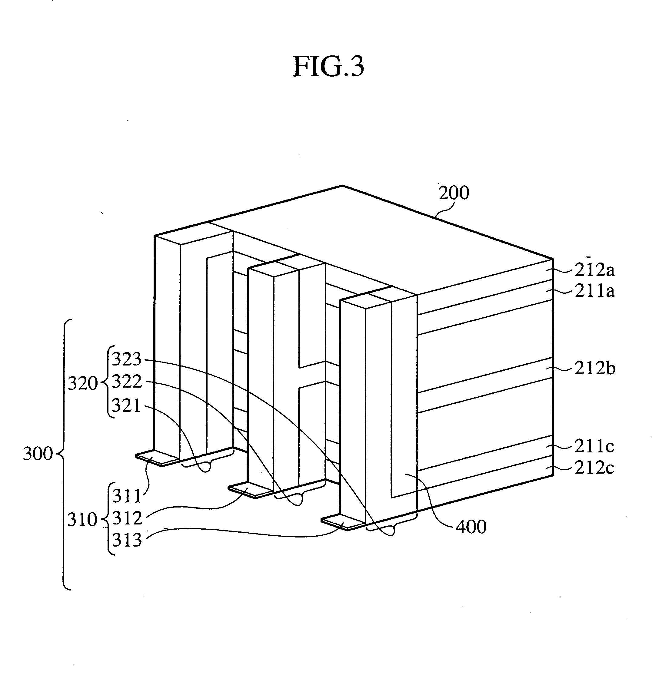
[0025]As shown in FIG. 1, the laminate type battery has a substrate 100 on which a plurality of layers is stacked. These layers are configured to form a power generating element 200, an electric circuit portion 300 and an insulating portion 400 when stacked. In other words, each of the layers is patterned so that the power generating element 200, the electric circuit portion 300 and the insulating portion 400 are formed by stacking these layers. Specifically, each of the layers is patterned as shown in FIG. 5, and the laminate type battery is formed by stacking these layers.

[0026]The electric circuit portion 300 has electrode terminals 310 for connecting the laminate type battery to an external device, and circuitries 320 for connecting the electrode terminals 310 and the power generating element 200. The electrode terminals 310 are exposed outside, and the ...

second embodiment

[0060]An assembled battery according to the present invention is constituted in a manner that a plurality of the laminate type batteries of the first embodiment is provided on the same substrate and connected to each other either in series or parallel. This embodiment will be described hereinbelow with reference to the drawings, but description of the constituents corresponding to those of the first embodiment will be omitted.

[0061]In FIG. 8, a plurality of laminate type batteries 1000 is provided on the same substrate 100 and connected to each other by tabs 3000. In this embodiment, the plurality of laminate type batteries 1000 are connected to each other in series, and each of the tabs 3000 is connected to a cell controller 2000 by lines 4000. The tabs 3000 are wide metal thin films and the tab portion 3000 and the lines 4000 are made on the substrate 100. The tabs 3000 are made wide in order to minimize internal resistance.

[0062]The assembled battery 5000 according to this embodi...


PUM

PropertyMeasurementUnit
particle sizeaaaaaaaaaa
viscosityaaaaaaaaaa

Abstract

A laminate type battery comprises a substrate, a power generating element which has at least one single cell made by a positive electrode layer, an electrolyte layer and a negative electrode layer which are sandwiched by collecting layers from both sides thereof, and an electric circuit portion having electrode terminals which connect the collecting layers to an external device and circuitries which connect the collecting layers and the electrode terminals. In the battery, the power generating element and the electric circuit portion are formed by stacking a plurality of layers on the substrate, and each of the layers is configured such that the power generating element and the electric circuit portion are formed by stacking the layers.

Description

BACKGROUND OF THE INVENTION[0001]1. Field of the Invention[0002]The present invention relates to a laminate type battery formed by stacking a plurality of layers and to a method for manufacturing the same.[0003]2. Description of the Related Art[0004]There is a known bipolar battery which is constructed in a manner that bipolar electrodes are formed by applying a positive electrode material and a negative electrode material on both sides of a metal foil serving as a collector by the use of a coater, and a plurality of these bipolar electrodes sandwiches a plurality of electrolyte sheets. This bipolar battery is sealed by a laminate film, and at least two collectors are extended to the outside from the laminate film. These two collectors are connected to electrode terminals, enabling the battery and an external device to be connected to each other through the electrode terminals.SUMMARY OF THE INVENTION[0005]However, this bipolar battery has a construction in which many members are co...

Claims


Application Information

Patent Timeline
Patent Type & Authority Applications(United States)
IPC IPC(8): H01M4/82H01M4/139H01M6/40H01M6/42H01M6/48H01M10/04H01M10/05H01M10/058H01M10/0585H01M10/42H01M10/44H01M50/531H01M50/55H01M50/553
CPCH01M2/26Y10T29/49115H01M4/02H01M4/0404H01M4/0414H01M4/505H01M4/70H01M6/40H01M6/425H01M6/48H01M10/0413H01M10/0436H01M10/0445H01M10/052H01M10/425H01M10/441H01M2004/021Y02E60/122Y10T29/49112H01M2/30Y02E60/10H01M50/531Y02P70/50H01M50/55H01M50/553
Inventor HISAMITSU, YASUNARIHORIE, HIDEAKINEMOTO, KOUICHIOHSAWA, YASUHIKO
Owner NISSAN MOTOR CO LTD
Why Eureka
Try Eureka